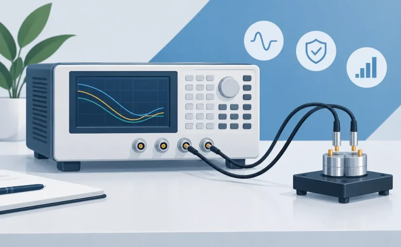
A 10 nH inductor, a 0.5 pF capacitor, or a milliohm-range impedance can disappear beneath the electrical behavior of the fixture holding it. Correct fixture measurement offsets are therefore not a cosmetic instrument setting. They are the correction that separates the component under test from the leads, contacts, adapters, and geometry used to reach it.
For production screening, failure analysis, incoming inspection, and precision rework, an offset error can create false rejects, mask damaged parts, or make two operators obtain different answers from the same component. The smaller the DUT value relative to fixture parasitics, the more disciplined the compensation process must be.
Why correct fixture measurement offsets matter
Every fixture adds impedance. Fixture conductors contribute series resistance and inductance. Open terminals, insulating surfaces, and adjacent conductors contribute shunt capacitance and leakage. At higher test frequencies, even a few millimeters of conductive path can become a meaningful portion of the measured impedance.
An LCR meter measures the total network present at its measurement terminals. Without correction, the displayed value includes the DUT plus the fixture’s residual electrical effects. A capacitor may read high because of parallel stray capacitance. A low-inductance component may read high because of lead and contact inductance. A low-resistance part may appear to have greater ESR because probe contact resistance is included in the result.
The practical question is not whether a fixture needs compensation. It is whether its residuals are significant compared with the required measurement uncertainty. A 100 uF electrolytic capacitor measured at a modest frequency may tolerate a simple compensated clip lead setup. A 0.2 pF RF capacitor or 5 nH inductor requires a far more controlled connection, short current paths, stable positioning, and verification against suitable standards.
The fixture model behind offset correction
Fixture correction generally addresses two different error paths: a series path and a parallel path. Understanding both prevents a common mistake: applying one correction and assuming every parasitic has been removed.
Open correction removes parallel residuals
With the fixture open and no DUT installed, the meter measures the residual admittance between the test terminals. This is usually dominated by stray capacitance and insulation leakage. The instrument uses that result to subtract the fixture’s parallel contribution from subsequent measurements.
Open correction is especially relevant for low-capacitance work. A few tenths of a picofarad from a socket, test board, or poorly spaced clip lead can be larger than the DUT itself. Keep the fixture in its normal measurement position during the open routine. Moving leads afterward changes the electric field and invalidates the captured offset.
Short correction removes series residuals
With the fixture terminals shorted at the DUT connection plane, the meter measures series resistance and inductance associated with leads, contacts, and conductor layout. The instrument then removes this series impedance from the measurement.
The short must be low impedance and physically representative. A long wire placed across the ends of a fixture is not an ideal short at 100 kHz or 250 kHz. It adds inductance and may introduce a correction that is worse than no correction. Use a wide, short, clean conductive short at the same location where the DUT terminals normally sit.
Load verification checks whether compensation is believable
Open and short routines correct a model. They do not prove that the model matches every DUT. Verification with a known, stable component or calibrated standard confirms that the corrected setup produces acceptable results at the selected frequency, test level, and measurement function.
This step matters when a fixture has spring contacts, a clamping mechanism, a relay matrix, or interchangeable adapters. Mechanical variation can change contact resistance and lead geometry. If verification shifts after several insertions, investigate the fixture before changing instrument settings.
Set the measurement conditions before capturing offsets
Offsets belong to a specific measurement configuration. Capture them only after selecting the test frequency, equivalent circuit, test signal level, and measurement mode used for the work. Changing conditions afterward can make a previously valid compensation unsuitable.
Frequency is the most obvious dependency. Inductance and capacitance parasitics have frequency-dependent reactance, while dielectric loss, skin effect, and contact behavior may also change. A fixture compensated for a 1 kHz capacitance measurement should not automatically be trusted for a 100 kHz ESR measurement.
Test level can also matter. Some components are voltage-sensitive, and some fixtures include contacts whose resistance improves or degrades with current. For semiconductor junctions, magnetic components, and high-value ceramic capacitors with DC-bias effects, define the measurement condition first and treat offset correction as part of that documented method.
Equivalent circuit selection deserves the same discipline. Series and parallel models can produce very different displayed values when dissipation factor or quality factor is low. Select the model appropriate to the component’s expected behavior at the test frequency, then capture the offsets for that method. Compensation cannot correct an unsuitable measurement model.
A controlled procedure for correct fixture measurement offsets
Start by inspecting the complete measurement path. This includes the meter terminals, Kelvin connectors, tweezers or probes, adapters, fixture contacts, and any test board. Oxidation, flux residue, loose fasteners, damaged insulation, and unstable probe pressure create errors that no stored offset can reliably remove.
Allow the instrument and fixture to stabilize at the operating temperature when the work requires tight limits. Copper resistance, contact pressure, and insulation leakage can shift as a fixture warms. In a production environment, this is one reason to perform a quick verification check at the beginning of a shift and after a fixture change.
Set the intended frequency, signal level, bias condition if used, range behavior, and series or parallel function. Then perform the open correction with the fixture arranged exactly as it will be used. Keep operators’ hands away from sensitive open terminals during sub-pF work. Body capacitance can easily alter the reading.
Next, install the proper short at the DUT plane and perform the short correction. For Kelvin fixtures, preserve the force and sense geometry used in actual testing. A short placed upstream of the contact points does not correct the contact resistance and inductance downstream of that location.
Remove the short, install a verification standard, and record the measured result. Compare it with the standard’s value and allowable uncertainty at the test frequency. If the result is outside tolerance, do not repeatedly rerun correction hoping for a better number. Check the fixture, shorting method, contacts, cable routing, and selected measurement parameters.
For repeatable production work, document the correction procedure with enough detail that another technician can reproduce it. Include the fixture identification, meter model, connector type, frequency, test level, equivalent circuit, correction date, verification component, and acceptable limits. This converts a one-time adjustment into a controlled measurement process.
Fixture design choices that reduce the need for correction
Compensation is most effective when the fixture is already electrically disciplined. It is not a substitute for good fixture design. Keep the DUT connection plane close to the measurement terminals, minimize loop area, separate high and low conductors appropriately, and avoid unnecessary adapters.
For low resistance and low inductance, four-terminal Kelvin connections are often essential. Separating current force from voltage sense minimizes the effect of lead and contact resistance on the sensed DUT voltage. However, Kelvin connections do not eliminate inductance created by a large current loop. The physical layout still controls high-frequency performance.
For low-capacitance work, use short, rigid connections and stable insulating materials with low leakage. A fixture that changes shape when a lid closes, a probe is pressed, or a cable is moved can change its capacitance enough to compromise sub-pF measurements. Guarding may be appropriate in specialized high-impedance applications, but it must be designed around the instrument’s measurement architecture rather than added casually.
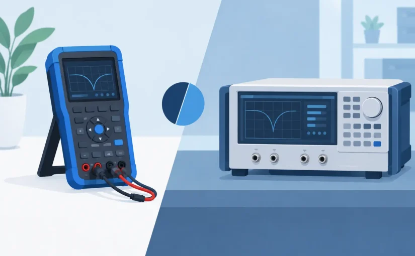
Direct-contact instruments can reduce the fixture path substantially for small SMD components. Smart Tweezers® are particularly useful when the goal is fast component identification or in-circuit comparison with minimal lead length. Even then, clean tips, consistent contact pressure, and a zeroing routine remain necessary when measuring near the lower limits of capacitance, inductance, or resistance.
When offsets should be repeated
Repeat correction whenever the electrical or mechanical measurement path changes. That includes changing adapters, replacing probes, repositioning cables, cleaning or replacing contacts, moving from one fixture insert to another, or changing frequency and test mode. A dropped fixture or a newly tightened screw can be enough to justify verification.
Time is another factor. A stored correction may remain suitable for a stable, enclosed fixture, but high-throughput sockets and spring probes wear. Humidity, contamination, and thermal cycling also change leakage and contact behavior. The right interval depends on the required uncertainty and process risk, not on a universal calendar rule.
Treat an offset as a measurement asset with a defined scope. When that scope changes, recapture it. This habit keeps the instrument reading tied to the DUT rather than to the unexamined behavior of the fixture around it.
The fastest route to dependable low-value measurements is not more averaging or a more impressive display resolution. It is a fixture whose residuals are understood, corrected at the DUT plane, and verified under the same conditions used to make the pass or fail decision.