How to Calibrate an LCR Meter for Reliable Results

A 10 nH inductor, a 0.5 pF capacitor, and a low-ESR ceramic capacitor can all be overwhelmed by the measurement system around them. Lead inductance, fixture capacitance, contact resistance, cable motion, and temperature drift can become larger than the component under test. That is why knowing how to calibrate an LCR meter is not simply an administrative task. It is the process that makes low-value measurements defensible, repeatable, and useful for engineering or production decisions.

Calibration is often used loosely to describe several different operations. A proper workflow separates instrument adjustment, fixture compensation, performance verification, and traceable calibration. Each serves a different purpose, and confusing them can create false confidence in a measurement result.

What LCR Meter Calibration Actually Corrects

An LCR meter measures impedance and derives parameters such as inductance, capacitance, resistance, ESR, dissipation factor, and quality factor. The displayed value is affected by the instrument’s internal measurement circuitry and by everything between that circuitry and the device under test.

Internal calibration addresses the meter itself. Depending on the model, it may include adjustment against internal references or external precision standards. Fixture compensation, by contrast, characterizes the residual impedance of the test leads, Kelvin clips, probes, or test fixture. It removes or minimizes errors introduced by the measurement path.

A third operation, verification, checks whether the complete system measures known standards within the required tolerance. Verification does not necessarily adjust anything. It documents that the meter, fixture, settings, and operator process are producing acceptable results.

For a lab operating under ISO-based quality procedures, aerospace maintenance requirements, or controlled manufacturing documentation, traceable calibration is a formal service performed against standards with a documented uncertainty chain. Daily open-short compensation is still necessary, but it does not replace a calibration certificate.

Before You Calibrate an LCR Meter

Start with the manufacturer’s procedure for the specific instrument. Calibration menus, allowable standards, warm-up requirements, and adjustment protections vary substantially between handheld meters, bench instruments, and direct-contact tweezer meters. Do not attempt an internal adjustment with improvised components unless the procedure explicitly permits it.

Allow the meter to reach thermal stability before any precision work. A typical instrument may require 15 to 30 minutes of warm-up, although the specified interval in the manual controls. If the meter was moved from a cold receiving area into a warm lab, allow the entire instrument, fixture, and standards to stabilize at the measurement environment.

Set up the same measurement conditions that will be used for the work. This includes test frequency, AC test level, DC bias if applicable, equivalent circuit mode, measurement speed, and range control. A capacitor measured at 1 kHz with a 1 V test signal is not necessarily comparable to a result acquired at 100 kHz with a lower signal level. For inductors and ferrites, test amplitude can also change the result through core nonlinearity.

Inspect and clean the contacts before compensation. Oxidized Kelvin clips, worn probe tips, flux residue, finger oils, and damaged cables add unstable resistance and leakage paths. For direct-contact SMD testing, clean tweezer tips and verify that the tips are aligned, insulated from one another, and mechanically secure. A precision meter cannot compensate for intermittent contact pressure.

The Open, Short, and Load Sequence

Most practical LCR measurement systems use open and short compensation. Higher-accuracy applications may add a load compensation or verification step using a known impedance standard.

Perform an open compensation

With nothing connected between the measurement terminals, run the meter’s open calibration or open compensation function. The instrument measures parasitic capacitance, leakage, and coupling in the fixture or cable assembly.

Keep the fixture in its intended physical position. Cable routing matters at high frequencies and when measuring fractions of a picofarad. Moving the leads after open compensation changes their distributed capacitance and inductance. For shielded fixtures, ensure the shield and guard connections match the manufacturer’s configuration before running the routine.

An open reading that appears unstable is a warning sign. Look for contaminated insulation, excessive humidity, damaged cable dielectric, an unshielded fixture near mains wiring, or a loose connector. Do not accept a drifting open result simply because the meter completes the routine.

Perform a short compensation

Next, connect the designated low-inductance short standard at the exact measurement plane. For Kelvin terminals, use the manufacturer’s shorting plate or a purpose-built, very low-impedance short. Avoid a length of hookup wire. Even a short wire introduces inductance that becomes significant at 100 kHz or 250 kHz.

Run the short compensation function and wait for completion. This routine characterizes residual series resistance and inductance in the connections. It is especially consequential for low-resistance, low-ESR, and low-inductance measurements.

The short standard must make repeatable, low-resistance contact. If the reported short resistance changes when you gently touch the fixture, the issue is mechanical or contamination-related, not a calibration problem. Correct the connection and repeat both open and short compensation.

Use a load standard when the application demands it

A load standard is a known capacitor, resistor, inductor, or precision impedance module measured near the value and frequency of interest. It helps reveal errors that open and short compensation cannot fully expose, including range-specific gain errors, nonlinearity, incorrect equivalent-circuit selection, and fixture behavior under actual load.

For example, a production process screening 0402 capacitors around 10 pF should verify with a stable standard near 10 pF, not only with a 1 µF reference. A repair technician evaluating milliohm-level ESR should verify with a low-resistance standard in the same operating range. Measurement confidence is strongest when the verification point resembles the component and conditions being evaluated.

Select the Right Equivalent Circuit and Test Conditions

Calibration cannot correct a poor model choice. LCR meters commonly provide series and parallel equivalent modes. In a series model, the meter expresses loss as series resistance or ESR. In a parallel model, it expresses loss as parallel resistance. The same physical component can display very different resistance values in the two modes while still representing the same impedance.

As a practical rule, low-impedance components are often evaluated in series mode, while high-impedance capacitive or resistive components are commonly evaluated in parallel mode. The correct choice depends on the component’s impedance, construction, specification method, and test frequency. Match the customer drawing, component datasheet, or internal test method rather than selecting a mode by habit.

Frequency selection deserves the same discipline. A 1 µF X7R MLCC can show a substantially different capacitance at 1 kHz than at 100 kHz. An inductor’s inductance and Q can change across frequency, while self-resonance may make a nominal inductor appear capacitive above its resonant point. Record frequency with every critical result.

How to Calibrate an LCR Meter in a Controlled Workflow

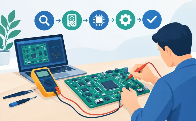
For routine bench or production use, the most effective process is short and repeatable. First, warm up the meter and inspect the fixture. Then select the approved test setup, run open and short compensation at the required frequency, and verify the system with a known standard. Finally, measure a control component or reference sample before releasing the station for use.

Repeat fixture compensation whenever the measurement path changes. That includes changing cables, replacing Kelvin probes, installing a different SMD fixture, changing probe spacing, or moving a sensitive fixture enough to alter lead geometry. For direct-contact instruments such as LCR-Reader and Smart Tweezers® devices, tip condition and spacing are part of the measurement path and should be checked accordingly.

In high-volume work, define recalibration triggers rather than relying only on a calendar. Useful triggers include a fixture change, a failed control sample, an instrument drop, a major temperature change, suspicious results, or a shift change in a tightly controlled process. Daily verification may be sufficient for one application; another may require verification at the start of every lot.

Document Results That Can Be Defended

A calibration record should identify more than the meter’s serial number. It should capture the instrument model, fixture or probe configuration, calibration date, operator, ambient conditions when relevant, test frequencies, standards used, measured values, allowable tolerances, and pass/fail outcome.

For formal traceability, retain the external calibration certificate and confirm its scope. A certificate for capacitance at one range or frequency does not automatically validate every parameter, range, and frequency used in your process. Review the reported points, uncertainty, environmental conditions, and due date against your actual measurement requirements.

When a verification standard falls outside tolerance, do not compensate by adjusting acceptance limits without an engineering decision. First repeat the test after cleaning contacts and re-running compensation. Then isolate the source by checking the standard, fixture, cable, and instrument separately. This approach prevents a damaged fixture from being misdiagnosed as meter drift.

Reliable LCR measurement is built at the measurement plane, not at the display. Treat open-short compensation, known-standard verification, and disciplined documentation as part of every test method, and even the smallest component values become far easier to trust.

Bluetooth LCR Meter Data Logging for Engineers

A component value written on a bench note is difficult to audit, easy to transpose, and nearly impossible to compare across a production lot. Bluetooth LCR meter data logging turns each measurement into usable engineering evidence: a record tied to a component, test condition, operator, time, and decision. For SMD inspection, incoming quality control, repair validation, and field troubleshooting, that difference can eliminate a large amount of repeated work.

The value is not Bluetooth by itself. The value is preserving a valid measurement without slowing the person making it. A portable LCR meter with direct-contact probes can identify and characterize a component at the point of work, while wireless transfer moves results to a phone, tablet, or computer for review and retention. Done correctly, the process combines handheld speed with the traceability normally expected from a more formal test station.

What Bluetooth LCR Meter Data Logging Should Capture

A useful log is more than a column of capacitance, inductance, or resistance values. The measurement must retain enough context for another engineer to understand what was tested and whether the result is comparable to a specification or a previous reading.

At minimum, a record should include the measured primary parameter, the secondary parameter, the test frequency, and the equivalent circuit model used by the instrument. Depending on the device under test, the secondary parameter may be ESR, dissipation factor, quality factor, phase angle, or DC resistance. A 10 µF ceramic capacitor measured at 1 kHz under one mode is not necessarily comparable to a measurement taken at 100 kHz under another mode. The data file should make that distinction visible.

Timestamp, device identification, instrument serial number, and operator or work-order identification add practical value. In a repair department, these fields establish what was checked before a board was released. In incoming inspection, they support lot-level comparisons. In a lab, they let a designer return to a suspect component weeks later without reconstructing the original conditions from memory.

A well-designed workflow also records pass/fail limits or a disposition field. Raw values matter, but the engineering decision matters too. A technician screening reels of capacitors may need to flag parts that fall outside a defined capacitance and ESR window, while a failure-analysis engineer may simply collect distributions before setting limits.

Why Wireless Logging Changes the Measurement Workflow

Manual entry creates a hidden bottleneck. It divides attention between component handling, reading the display, typing values, and labeling samples. That interruption becomes significant when inspecting 0402 and 0201 devices, evaluating a mixed tray of recovered components, or comparing many channels on a board.

Bluetooth transfer allows the operator to keep the meter where it belongs: at the DUT. A direct-contact tweezer instrument can measure an unmounted SMD component without fixture setup, and the receiving application can capture results as measurements are taken. This is particularly effective when the instrument automatically identifies the component type and selects an appropriate measurement function.

The gain is not limited to speed. Wireless logging reduces transcription errors and produces a time-ordered data set that can expose trends. If ESR begins drifting upward across a batch, or if a group of nominally identical inductors separates into two value populations, the pattern is easier to see in recorded data than in a stack of handwritten values.

For field service, Bluetooth also separates the test point from the documentation point. A technician can reach a densely populated assembly or a mounted harness connection while the receiving device remains accessible. That is useful when working around large systems, environmental chambers, or equipment where a laptop cannot sit next to the measurement location.

Measurement Integrity Comes Before Data Volume

Logging thousands of records does not improve a weak measurement process. It can merely preserve error at higher speed. Before starting a run, establish the test conditions that correspond to the component specification or the diagnostic objective.

Select the Frequency and Model Deliberately

Capacitors, inductors, and resistive components behave differently as frequency changes. A capacitor’s apparent capacitance and loss may vary with test frequency, dielectric, bias conditions, and construction. An inductor’s inductance and Q can shift near self-resonance. For this reason, the test frequency should not be treated as a convenience setting.

Use the frequency specified on the component data sheet when performing acceptance testing. When troubleshooting, select frequencies that reveal the suspected failure mechanism, then record them consistently. For example, ESR evaluation at a relevant higher frequency may be more informative than a single low-frequency capacitance reading. Instruments capable of test frequencies up to 250 kHz can provide a more relevant view of high-frequency component behavior, but only when the chosen frequency matches the question being asked.

The equivalent model also matters. Series and parallel representations can produce substantially different reported values when losses are significant. The log should preserve the selected model rather than leaving future reviewers to infer it.

Control Contact and Parasitics

At sub-picofarad capacitance and nanohenry-scale inductance levels, contact geometry is part of the measurement circuit. Lead length, probe separation, contamination, poor contact pressure, and nearby conductive objects can influence the result. The advantage of tweezer-style direct contact is that it minimizes unnecessary lead length and lets the operator measure very small components rapidly, but correct technique remains essential.

Keep contacts clean, allow the DUT to settle in the probe tips, and avoid changing orientation halfway through a comparison run. Use open and short compensation procedures when applicable, especially for very low values or when accessories and probe configurations change. If a component is being measured in circuit, recognize that parallel paths and surrounding circuitry can dominate the apparent result. A clean log should identify in-circuit readings as such instead of presenting them as isolated component values.

Maintain Calibration Discipline

Bluetooth is a data path, not a substitute for calibration. The reported value can only support a quality decision when the instrument’s accuracy is appropriate for the tolerance being evaluated and its calibration status is controlled.

For production and laboratory work, retain the calibration date, certificate reference where required, and instrument serial number with the test record or work order. Traceable calibration supports confidence in the instrument, while verification with known standards helps catch a damaged probe, contaminated contact surface, or unsuitable setup before a large test run begins. LCR-Reader instruments are designed for precision handheld measurement, but the same metrology discipline applies to every portable meter in a controlled process.

Build a Logging Method That Fits the Job

There is no single ideal logging rate or record format. A repair technician validating a replacement capacitor may need only a few records attached to a service ticket. A manufacturing engineer screening a reel may need continuous capture, sample identifiers, lot information, and exportable data for statistical review.

For repetitive component screening, create a fixed sequence before measurement begins. Label the tray positions or sample containers, define the pass/fail criteria, and confirm frequency, model, and range behavior on a known-good reference part. Then measure in a consistent order. This prevents a common problem in which excellent data is collected but later cannot be associated with the correct component.

For design characterization, include environmental and device context. Record part number, date code, package size, board location if applicable, and any relevant temperature or bias condition. Bluetooth logging can capture electrical values efficiently, but those supporting fields are what turn a set of readings into a useful design record.

For intermittent faults, use time-based capture carefully. A continuous stream can reveal a capacitance drop, resistance jump, or inductance shift caused by flexing, heating, vibration, or connector movement. However, a high sample count can obscure the event if the records lack annotations. Mark the action being performed – such as heat applied, cable moved, or load enabled – so the electrical transition has diagnostic meaning.

Bluetooth Limits and Practical Controls

Wireless logging has trade-offs. Bluetooth range is affected by metal enclosures, dense equipment racks, interference, and the position of the receiving device. A connection loss can create missing records, delayed transfer, or uncertainty about whether a reading was captured. In a controlled workflow, the operator should be able to verify the receiving application’s connection state and confirm record count before closing the job.

Battery state also deserves attention. A handheld instrument and its paired device may both run for a normal inspection session, yet a long screening run or field shift changes the calculation. Start critical work with adequate charge, and determine whether the application buffers readings locally if the wireless connection is briefly interrupted.

Data security depends on the work environment. For general component evaluation, a standard paired connection may be appropriate. For restricted programs, determine whether wireless devices are permitted, where measurement files are stored, who can access them, and how records are transferred into the approved quality system. Portability should not bypass documentation controls.

Turning Logs Into Engineering Decisions

The strongest use of logged LCR data is comparison. Compare measured values against tolerance limits, golden samples, prior production lots, or the distribution of neighboring components on the same assembly. A single reading may identify an obvious open, short, or incorrect value. A logged series is far better at revealing subtle drift and mixed inventory.

Review the primary and secondary parameters together. Two capacitors can show similar capacitance while having very different ESR or dissipation factor. Two inductors can meet an inductance target while separating sharply in Q or DC resistance. Those secondary measurements often explain why a circuit behaves incorrectly under load or at frequency.

Use the data to make the next test more targeted. If a reel shows a broad capacitance spread, verify the part number, dielectric, and test conditions before rejecting it. If a repaired board still fails despite nominal component values, compare loss parameters and in-circuit results against a known-good board. The log should narrow the problem, not become an archive no one revisits.

A disciplined Bluetooth logging process gives portable LCR measurement a longer working life. The value no longer disappears when the display changes. It becomes evidence an engineer can review, challenge, correlate, and use to make the next pass/fail decision with greater confidence.

How to Measure Low Inductance Accurately

A 10 nH inductor does not look like 10 nH to an instrument unless the test setup is designed to see it. A few millimeters of lead length, a test clip, or an uncorrected fixture can contribute inductance comparable to, or larger than, the device under test. That is the central challenge in how to measure low inductance: the measurement system becomes part of the result.

For engineers evaluating small RF inductors, ferrite beads, current-sense paths, PCB structures, or sub-microhenry power components, a credible result requires more than connecting an LCR meter and reading the display. The connection method, equivalent circuit model, test frequency, compensation routine, and handling discipline all determine whether the reading is useful.

Define what “low inductance” means for the job

Low inductance is application-dependent. In a power design, 100 nH may be a critical value. In RF work, 100 nH is routine, while a few nanohenries can determine matching performance. From a measurement perspective, the difficult range begins when fixture and contact parasitics are no longer negligible relative to the DUT.

The basic relationship is familiar:

`X_L = 2πfL`

A 10 nH inductor has a reactance of only about 0.0063 ohms at 100 kHz. At that level, contact resistance, residual fixture inductance, noise, and phase error can overwhelm the reactive signal. Raising frequency increases inductive reactance and can improve sensitivity, but it also moves the component closer to self-resonance and introduces frequency-dependent core and conductor losses. There is no universally correct test frequency.

Start with the component’s intended operating region and the manufacturer’s specified test conditions. If you are qualifying incoming parts, use the datasheet frequency whenever the meter and fixture can support it. If you are characterizing a board feature or an unknown component, measure at several frequencies and record the conditions with the result.

Use the correct equivalent circuit

For most low-value inductors measured below self-resonance, select a series model. The series representation reports inductance as Ls and loss as series resistance, Rs. This usually reflects physical reality for a small wire-wound inductor, ferrite bead, trace segment, or low-impedance coil, where winding resistance and contact resistance are in series with the inductive element.

Parallel mode can produce misleading values for low-impedance devices. It is more suitable when the DUT behaves primarily as a high-impedance parallel network. If the meter automatically selects a model, verify that the selected mode matches the device and frequency. Automatic identification is useful for rapid screening, but it does not replace engineering judgment when the value approaches the fixture’s residuals.

Also watch the quality factor, Q, or dissipation factor, D. A stable Ls reading with implausible loss data may indicate poor contact, a frequency outside the component’s useful range, or a measurement that is nearing the instrument’s resolution limit.

How to measure low inductance with the right connection

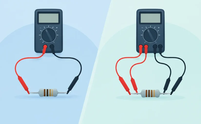
Two-wire leads are rarely adequate for nanohenry work. Their loop area adds inductance, and the same conductors carry test current and sense voltage. Use a four-terminal Kelvin connection whenever the instrument and fixture support it. Force terminals drive the test current; sense terminals measure the voltage directly at the DUT. This reduces the influence of lead and contact resistance.

For AC impedance measurement, four-terminal-pair techniques provide additional control of return-current paths and terminal effects. In a handheld workflow, a short, rigid Kelvin fixture or direct-contact tweezer arrangement can provide the practical equivalent benefit: minimize separation, eliminate unnecessary lead length, and place the sensing points as close to the component body as possible.

The geometry matters as much as the terminal count. Keep force and sense conductors short and closely coupled. Avoid long flying leads, open clip jaws, and wide current loops. Do not extend a precision fixture with ordinary jumper wire simply because the DUT is inconvenient to reach. The extension may become the dominant inductor.

For small SMD inductors, direct contact to the end terminations is preferable to probing through long adapters. Smart Tweezers® instruments are particularly effective for rapid, direct-contact screening of small components, provided the contacts are clean and the measurement is performed within the instrument’s specified low-inductance capability.

Compensate the fixture at the measurement plane

Compensation is not optional when the target value is comparable to fixture parasitics. The objective is to establish the reference plane at the exact location where the DUT will be connected.

Begin with an open compensation. With the fixture arranged exactly as it will be used, but with no DUT installed, run the instrument’s open correction. This characterizes residual shunt effects, primarily stray capacitance and leakage. For low inductance, the short correction is usually more consequential. Install a low-inductance short standard across the DUT connection points and run short compensation to characterize residual series impedance.

A short standard must actually be short at the measurement frequency. A long wire link is not a valid standard for nanohenry work. Use a wide, compact conductive link or a purpose-designed calibration short that matches the fixture geometry. Re-run compensation whenever you change adapters, contact spacing, cable position, or frequency range.

Compensation removes repeatable fixture behavior. It cannot correct unstable contact pressure, oxidation, mechanical movement, or a poor fixture design. If readings shift when the component is gently touched, the setup needs improvement before more digits have any meaning.

Select frequency and test level deliberately

A higher frequency increases the reactance of a small inductor and often makes the value easier to resolve. But frequency also changes the DUT. Ferrite materials are dispersive, skin effect raises AC resistance, and parasitic capacitance can push the component toward self-resonance. Near self-resonance, an LCR meter may display a value that is mathematically computed but no longer represents a simple inductive element.

Measure at the datasheet frequency first. Then take readings at lower and higher available frequencies. A well-behaved inductor will normally show a plausible trend in Ls, Rs, and Q. If inductance rises sharply, falls abruptly, changes sign, or becomes highly sensitive to contact position, investigate self-resonance, fixture effects, or model selection.

Test amplitude matters for magnetic components. A ferrite-core inductor can show different inductance at different AC drive levels and DC bias conditions. Standard LCR measurement is a small-signal result. If the part will operate with substantial DC current, the small-signal reading does not establish inductance under load. Use a bias-capable characterization method or evaluate the part in its intended circuit condition.

Verify the result instead of trusting one reading

Repeatability is the first credibility check. Remove and reconnect the DUT several times. If the spread is significant relative to the tolerance being evaluated, inspect the contacts, fixture rigidity, compensation, and test frequency. Record the median or average only after the spread is understood.

A second check is comparison with a known standard or a trusted sample. This does not need to be an identical value. A stable low-inductance reference near the range of interest confirms that the instrument, fixture, and correction workflow are behaving as expected. For production or quality systems, use calibrated standards and maintain documented verification intervals.

Finally, distinguish component inductance from circuit inductance. Measuring a part while it remains installed on a PCB commonly produces the impedance of parallel paths, attached capacitors, semiconductor junctions, and copper geometry. In-circuit readings can be useful for comparative troubleshooting, but they are not automatically the component’s standalone inductance. Isolate at least one terminal when the specification requires a definitive value.

Build a measurement record that can be repeated

A low-inductance result should always travel with its conditions: instrument model, calibration status, Ls or Lp mode, test frequency, test voltage or current, fixture type, compensation state, and whether the DUT was isolated. For a 5 nH result, those details are not administrative overhead. They define what was measured.

When the fixture is short, the reference plane is controlled, and the test conditions match the engineering question, low-inductance measurement becomes repeatable rather than optimistic. Treat every nanohenry as a system-level measurement, and the number on the display becomes a result your design, inspection, or failure analysis team can act on.

How to Measure Sub Picofarad Capacitance

A 0.2 pF capacitor is rarely difficult because of its physical size alone. The difficult part is that the fixture, probe spacing, solder mask, cable motion, humidity, and even a nearby hand can contribute capacitance of the same order. To understand how to measure sub picofarad capacitance, treat the test setup as part of the measurement system, not as an invisible accessory.

At these values, a display reading is only useful when the residual capacitance of the measurement path is characterized, compensated, and kept stable. The goal is not simply to obtain a number. It is to separate the device under test from the parasitic capacitance surrounding it and determine whether the result is repeatable enough for an engineering or quality decision.

Why sub-pF measurements are different

Capacitance below 1 pF is common in RF matching networks, high-speed PCB structures, semiconductor packages, sensor elements, small variable capacitors, and intentional or unintentional coupling paths. It also appears where engineers may not expect it: an open fixture, a probe tip pair, a connector, or two adjacent traces can easily introduce fractions of a picofarad.

The electrical signal is small. Capacitive reactance follows the relationship Xc = 1 / (2πfC). A 0.1 pF capacitance has a reactance of approximately 15.9 Mohm at 100 kHz and 6.37 Mohm at 250 kHz. That high impedance means leakage current, surface contamination, input bias effects, and stray coupling can distort the calculated capacitance.

This is why resolution alone is not a measurement specification. A meter may display 0.1 pF increments, but the useful result depends on basic accuracy, repeatability, test frequency, open compensation quality, fixture stability, and the instrument’s ability to reject or account for parasitic effects.

How to measure sub picofarad capacitance correctly

Begin with a capacitance instrument designed to operate in the required range and frequency band. For low-value capacitance, an LCR meter or precision handheld component analyzer with a specified sub-pF range is preferable to the capacitance function of a general-purpose DMM. A typical DMM capacitance mode is useful for larger capacitors but generally lacks the test frequency, compensation controls, connection geometry, and low-level measurement performance needed for reliable sub-pF work.

Select a test frequency that reflects the application. Higher frequencies reduce capacitive reactance and can improve signal discrimination for extremely small values. However, frequency also changes what is being measured. A real component may include ESR, inductance, dielectric loss, electrode effects, and fixture resonance. A 0.5 pF RF capacitor measured at 1 kHz, 100 kHz, and 250 kHz may not produce identical results, and that difference can be meaningful rather than an instrument error.

Before connecting the component, configure the instrument for the correct equivalent circuit model. For small capacitors with high impedance, parallel capacitance and parallel resistance or dissipation factor are often appropriate representations. The correct model depends on component construction and frequency, so use the model specified by the component manufacturer or your internal test method when one exists.

Perform open compensation at the measurement plane

Open compensation is the central control for sub-pF measurement. With the fixture or probes in their normal operating position but with no device connected, run the instrument’s open correction routine. This records the fixture’s residual capacitance and admittance so the meter can subtract it from subsequent readings.

The words “normal operating position” matter. If you compensate with probe tips separated by 3 mm and then measure with them separated by 1 mm, the parasitic capacitance has changed. Likewise, bending leads, moving a cable, changing a coax adapter, or switching fixtures after compensation can invalidate the correction.

For direct-contact tweezers, hold the jaws in the same orientation and spacing used for the actual component. For a PCB fixture, perform compensation with the board connector, test pads, guard structure, and cables installed exactly as they will be during testing. LCR-Reader instruments built for direct SMD contact can reduce lead length and handling variability, but compensation and stable technique remain essential.

A short correction may also be required when the instrument and fixture support it, particularly where series impedance of leads or contacts is significant. In a sub-pF application, the open correction usually has the greatest influence, while short correction helps establish the complete measurement reference plane.

Control the fixture, probes, and surrounding field

Long unshielded leads are the enemy of low-capacitance measurement. Their capacitance can exceed the DUT by orders of magnitude, and their movement changes the result. Use the shortest practical connection path. Rigid, clean, shielded fixtures are more repeatable than loose clip leads.

Guarding is equally valuable. A driven guard conductor surrounding a high-impedance node reduces leakage and limits capacitive coupling to nearby conductive surfaces. In a dedicated fixture, guard traces should be designed around sensitive nodes where practical. Coaxial or triaxial connection methods may be appropriate for laboratory setups, but the benefit depends on whether the meter and fixture support a true guard connection.

Keep hands, tools, and conductive objects away from the measurement node during acquisition. Body capacitance can be tens to hundreds of picofarads, and even indirect coupling can shift a reading that is attempting to resolve tenths of a picofarad. A grounded work surface and consistent fixture placement improve repeatability.

Surface condition matters as well. Flux residue, finger oils, moisture, and ionic contamination create leakage paths that appear as parallel conductance and can corrupt the capacitance calculation. Clean the fixture and test pads using an appropriate electronics cleaning process, allow them to dry completely, and avoid touching high-impedance contacts.

Measure the component, then prove the result is stable

Connect the DUT without changing fixture geometry. Allow the reading to settle, then record capacitance together with test frequency, equivalent-circuit mode, correction state, and any reported dissipation factor or parallel resistance. A capacitance value without these conditions is often not sufficient for comparison across operators, instruments, or production lots.

Repeat the measurement several times, removing and reconnecting the part if the workflow permits. The spread is as informative as the average. If a nominal 0.3 pF part reads 0.31 pF, 0.32 pF, and 0.31 pF, the setup is behaving differently than one that reads 0.18 pF, 0.46 pF, and 0.27 pF. The latter condition calls for fixture investigation before judging the component.

For production or incoming inspection, establish a measurement system analysis using known low-capacitance standards or characterized reference artifacts. Verify repeatability across operators and fixtures, not only against a single displayed value. Traceable calibration confirms instrument performance within stated conditions; it does not automatically validate a contaminated, unguarded, or mechanically unstable test fixture.

Distinguish a capacitor from a parasitic structure

An isolated precision capacitor is the simplest case. Measuring capacitance on an assembled PCB is more complex because adjacent traces, IC pins, ESD structures, vias, and planes create parallel and series paths. An in-circuit result may be useful for screening or fault isolation, but it may not equal the capacitor’s datasheet value.

If the reading is unexpectedly high, first suspect fixture residuals, probe spacing, nearby copper, and parallel circuit paths. If it is unstable, suspect loose contact, cable motion, contamination, inadequate settling time, or environmental coupling. If the value changes substantially with frequency, investigate the DUT’s parasitics and equivalent-circuit behavior before declaring a failure.

For PCB-level work, compare a known-good board or an adjacent identical channel under identical test conditions. That comparison often provides a faster and more defensible pass/fail decision than attempting to infer the exact capacitance of one embedded network.

Common practices that produce misleading readings

The most frequent mistake is measuring a sub-pF component immediately after connecting uncorrected leads. The instrument is then measuring the component plus fixture capacitance, not the component alone. Another common error is assuming the lowest available test frequency is always best. At very low capacitance, higher frequency may improve sensitivity, provided it remains appropriate for the application and the fixture does not introduce resonance or instability.

Avoid treating the last displayed digit as guaranteed information. A stable 0.26 pF reading can be more useful than a fluctuating display that alternates between 0.1 pF and 0.4 pF, even if both instruments advertise similar resolution. Evaluate uncertainty through repeat measurements and reference checks.

Finally, do not interchange test accessories casually. A different tweezer tip, Kelvin adapter, cable, or PCB fixture changes the measurement system. Re-run compensation whenever the physical setup changes.

Sub-pF capacitance work rewards disciplined setup more than elaborate procedure. Establish a fixed measurement plane, compensate it correctly, use the shortest and cleanest possible connections, and document frequency and repeatability. When those controls are in place, fractions of a picofarad become a practical engineering measurement rather than a number dominated by the test fixture.

How to Measure Sub-pF and Sub-10 nH Components with Handheld LCR Tweezers

How to Measure Sub-pF and Sub-10 nH Components with Handheld LCR Tweezers | Siborg Systems

Tweezer-style LCR meters have revolutionized surface-mount device (SMD) troubleshooting since Siborg introduced the original Smart Tweezers in 2005. Today’s advanced instruments—including the LCR-Reader-MPA, R2, and R3—boast test frequencies up to 250 kHz, 0.1% basic accuracy, and comprehensive all-in-one multimeter capabilities.

However, engineers and technicians working with ultra-small RF components face a well-known physical limitation inherent to all tweezer-style instruments: parasitic capacitance and inductance in unshielded test leads.

To solve this challenge, Siborg Systems Inc. introduced patent-pending Open/Short Calibration Boards, enabling handheld tweezer meters to reliably measure passive components below 1 pF and 10 nH—territory previously reserved for expensive benchtop setups.

The Hidden Challenge of Tweezer Parasitics

Whenever an unshielded two-wire probe approaches a circuit component, parasitic fields form between the probe tips:

  • Parasitic Capacitance: The air gap between the tweezer arms acts as a tiny capacitor. As the tips move closer together to clamp a smaller component, this mutual capacitance shifts.
  • Parasitic Inductance: The physical loop created by the tweezer tines introduces residual series inductance.

In typical tweezer meters, parasitic offsets range from 0.014 to 0.249 pF for capacitance and 2.8 to 18.6 nH for inductance, depending directly on the distance between the tips.

While a 0.2 pF or 5 nH offset is negligible when measuring a 10 µF decoupling capacitor, it introduces catastrophic errors when qualifying ultra-small components. As Siborg demonstrated in IEEE publications (AutoTestCon 2022 and the IEEE Instrumentation & Measurement Magazine, August 2023), measuring an inductor below 10 nH without compensating for two-wire test fixture parasitics can lead to relative errors exceeding 100%.

How Siborg’s Offset Calibration Boards Work

Presented at Nepcon Tokyo and the SMTA International Conference in Minneapolis, Siborg’s proprietary calibration fixtures provide a repeatable, standard method for eliminating test-lead offsets.

The calibration boards are specialized dummy PCBs engineered with precision-spaced slots representing standard SMD footprints (such as 0201, 0402, 0603, and 0805):

  1. Geometry-Matched Compensation: Placing the tweezer tips into the exact footprint slot matching the target component fixes the probe spacing to that specific component width.
  2. Offset Nulling: The board allows the meter to determine the baseline parasitic offset at that exact mechanical spacing.
  3. Sub-pF Accuracy: By subtracting these offsets—or letting the meter’s firmware compensate automatically—measurement offsets drop below 0.01 pF for capacitance and 1 nH for inductance.
Parameter Standard Tweezer Offset With Siborg Calibration Board
Residual Capacitance 0.014 pF to 0.249 pF < 0.01 pF
Residual Inductance 2.8 nH to 18.6 nH < 1.0 nH
Smallest Reliable Limit ~10 pF / ~10 nH < 1 pF / < 10 nH

Running an Open/Short Calibration on LCR-Reader

On compatible instruments (such as the LCR-Reader-MPA, R2, and R3), executing a calibration cycle takes less than a minute:

  1. Insert the tips into the appropriate calibration slot on the board.
  2. Push and hold the control joystick to the right until you hear two beeps to initiate the calibration cycle.
Technique Tip: Grip pressure matters. Variations in hand pressure on the tweezer arms can shift readings by up to 0.005 pF or 0.5 nH. Maintaining consistent, gentle pressure during both calibration and measurement ensures maximum repeatability.

Benchtop Precision in Your Pocket

Evaluating high-frequency RF matching networks, precision oscillators, and avionics circuitry no longer demands hauling out a dedicated benchtop network analyzer or four-wire bridge.

By pairing high-frequency test capability (up to 250 kHz) with dedicated Open/Short Calibration Boards, Siborg’s LCR-Reader family bridges the gap between field portability and laboratory-grade metrology.

To learn more about the LCR-Reader product family and calibration accessories, visit lcr-reader.com.

How to Test Capacitor ESR With Confidence

A capacitor can measure close to its marked capacitance and still be the reason a power supply oscillates, an LED driver flickers, or a digital rail collapses under load. Equivalent series resistance, or ESR, exposes losses that a capacitance-only measurement can miss. Knowing how to test capacitor ESR correctly means controlling the test setup, selecting a meaningful frequency, and comparing the result to a relevant specification rather than treating one resistance value as universally good or bad.

What capacitor ESR measures

An actual capacitor is not an ideal capacitance. Its internal foil, electrolyte, terminations, dielectric losses, and current path contribute resistance and inductance. ESR is the resistive portion of that non-ideal behavior at a stated test frequency. It represents energy dissipated as heat when AC ripple current flows through the part.

For an aluminum electrolytic capacitor in a switching regulator, excessive ESR can create output ripple, poor transient response, and self-heating. For a multilayer ceramic capacitor, ESR is often extremely low, so fixture resistance and contact quality may dominate the measurement. Film capacitors, tantalum capacitors, polymer capacitors, and supercapacitors each have different expected ESR ranges and frequency behavior.

That last point matters. ESR is not a fixed DC resistance. A data sheet may specify impedance or ESR at 100 Hz, 120 Hz, 1 kHz, 10 kHz, or 100 kHz. A reading only has engineering value when its test frequency, signal level, temperature, and connection method are understood.

How to test capacitor ESR accurately

Begin with safety and component condition. Remove power from the circuit, discharge the capacitor through an appropriate resistor, and verify residual voltage with a meter. Never place an ESR meter directly across a charged capacitor. A stored charge can damage the instrument and create a serious safety hazard, particularly in high-voltage power supplies or large bulk capacitor banks.

For the most reliable result, test the capacitor out of circuit. This isolates the device from parallel capacitors, semiconductors, inductors, and low-resistance PCB paths that can distort an impedance measurement. In repair work, in-circuit ESR testing is often useful as a fast screening method, but it is not definitive. A suspicious in-circuit result should be confirmed after lifting one terminal or removing the component.

Use a meter that measures impedance parameters at a known AC test frequency, not a basic ohmmeter. A DC resistance range will initially show charging behavior and then may drift toward overload. That observation can identify a shorted capacitor, but it does not measure ESR. An LCR meter, dedicated ESR meter, or precision handheld instrument designed for component characterization applies an AC stimulus and calculates the equivalent series parameters.

Before connecting the capacitor, compensate the test fixture. Short the probes or Kelvin contacts and perform the instrument’s short correction if available. For measurements of low ESR, open correction can also be necessary to remove stray capacitance and leakage in the fixture. Compensation should be performed using the same leads, connector, probe spacing, and measurement range used for the test. A low-milliohm measurement made with uncompensated leads can be a measurement of the leads rather than the capacitor.

Direct-contact tweezer instruments are particularly effective for small SMD capacitors because they reduce lead length and allow stable contact at the terminals. For radial or large can capacitors, use short Kelvin clips when possible. The force and cleanliness of the connection matter: oxidized leads, probe pressure, and a loose clip can add resistance that looks exactly like capacitor ESR.

Select a test frequency that matches the decision

Match the test frequency to the component specification or its operating environment. If an electrolytic capacitor is specified at 120 Hz, measure near 120 Hz for incoming inspection against that limit. If the capacitor is used on a 100 kHz switching rail and its data sheet provides high-frequency impedance data, a higher test frequency is more representative of the application.

A single frequency cannot answer every question. Low-frequency testing is useful for comparison with many electrolytic data sheets, while higher-frequency measurements can reveal performance relevant to switch-mode power supplies. At sufficiently high frequency, lead and fixture inductance become significant. The measured parameter may transition from capacitive behavior toward resonance, and reporting only ESR without phase or impedance context can be misleading.

Control temperature and measurement time

ESR changes with temperature, especially in electrolytic capacitors. A cold capacitor can exhibit much higher ESR than it will at normal operating temperature. Conversely, a part warmed by ripple current may test favorably for a short time while still having limited remaining life. If the result is near a pass/fail limit, record ambient temperature and allow the part to stabilize before making a disposition.

Allow the instrument reading to settle, but do not confuse a stable display with a valid result. Auto-ranging meters can briefly change test conditions during range selection. Once the reading settles, confirm that the displayed equivalent model is series resistance and that the selected frequency is documented. In production or quality-control work, those settings belong in the test procedure, not in operator memory.

Interpreting an ESR reading

The correct benchmark is the manufacturer’s data sheet, preferably the maximum ESR or impedance specification at the same frequency and temperature. If no specification is available, compare the reading with a known-good component of the same series, voltage rating, capacitance, package size, and approximate age. Comparing unlike capacitor technologies is rarely useful.

High ESR is usually the failure mode technicians seek, but low ESR is not automatically proof of a healthy part. A shorted capacitor can read extremely low resistance, and a ceramic capacitor with a cracked termination may behave intermittently under mechanical stress despite a normal bench reading. Check capacitance, dissipation factor when available, leakage where applicable, and the circuit’s actual ripple waveform when the fault remains unresolved.

A practical interpretation might look like this: an electrolytic capacitor specified at 0.08 ohm maximum at 100 kHz should not be accepted based on a 0.08-ohm reading measured at 1 kHz with long clip leads. The apparent match is accidental because the measurement conditions differ. By contrast, a compensated four-wire measurement at the specified frequency provides a defensible basis for an acceptance decision.

In-circuit ESR testing: fast, but conditional

In-circuit testing is valuable when troubleshooting densely populated boards, particularly when access is limited or component removal risks pad damage. An ESR meter’s low AC test amplitude may avoid forward-biasing some semiconductor junctions, allowing rapid detection of a clearly degraded electrolytic capacitor without desoldering it.

The limitation is parallel impedance. Multiple capacitors on a power rail can make a failed unit appear acceptable because healthy capacitors lower the measured ESR. Parallel resistive paths can also force the reading downward. Inductors, transformers, protection devices, and IC output stages can produce results that do not represent the capacitor at all.

Treat an in-circuit measurement as strong evidence only when the result is clearly abnormal and the circuit topology supports the conclusion. If the reading is marginal, unexpectedly low, or inconsistent with symptoms, isolate the capacitor by lifting one lead or removing it. This is slower than probing in place, but it prevents a false pass from becoming a repeat repair.

Common errors that produce false ESR results

The most common error is using a two-wire connection for a very low-ESR device. With two wires, probe and contact resistance are included in the result. Kelvin measurement separates the current-carrying and voltage-sensing paths, greatly reducing this error. For milliohm-level work, it is not a luxury; it is a requirement.

Another error is ignoring capacitor technology and package size. A small ceramic capacitor may have ESR far below that of a similarly valued electrolytic capacitor, while a high-voltage film capacitor may exhibit different frequency behavior from either. Use the component’s construction and intended duty to set expectations.

Finally, avoid testing a component that has not been fully discharged or has been removed from a hot circuit without allowing it to cool. Good metrology begins before the probes touch the part. Clean contacts, controlled connections, correct compensation, and traceable instrument calibration determine whether the number on the display can support a repair, production, or failure-analysis decision.

For technicians and engineers who must move from board-level triage to defensible component data, the fastest workflow is not simply measuring ESR. It is measuring it under conditions that make the result repeatable, comparable, and actionable.

Best Tweezers for SMD Components That Measure

A 0201 capacitor can look perfectly placed, yet be open, cracked, incorrectly loaded, or simply the wrong value. At that scale, the best tweezers for SMD components are not defined only by whether they can pick up a part. They must give the operator controlled mechanical handling and, when troubleshooting or incoming inspection requires it, a dependable electrical connection at the component terminations.

For production placement, rework, failure analysis, and component verification, the right choice depends on the job. Fine hand tweezers excel at placement and alignment. Measurement tweezers add a different capability: direct-contact LCR testing that identifies and characterizes a component without leads, clips, or a large fixture. Treating both tools as interchangeable is a common source of slow work and uncertain results.

What the Best Tweezers for SMD Components Must Do

An SMD tweezer is working against several constraints at once. The tips must reach small terminations without obscuring the work area. Their closing force must be predictable enough to avoid launching a 0402 resistor across the bench or crushing a fragile ceramic capacitor. The body needs enough rigidity that tip alignment remains stable after repeated cycles.

Electrical requirements introduce another layer. Ordinary steel tweezers can hold a component, but they cannot establish a controlled, repeatable test interface. For resistance, capacitance, inductance, and ESR work, each tip must act as an isolated test terminal. The instrument must compensate for its own residual effects and present readings that are meaningful at the value being tested.

This distinction matters most at very low values. A fraction of a picofarad, a few nanohenries, or milliohms of contact resistance can be comparable to the component itself. A tool that is adequate for sorting 10 kΩ resistors may not be adequate for validating a low-inductance RF capacitor or a 1 nH inductor.

Start With the Actual SMD Task

Placement, rework, and visual inspection

For placing components, choose precision hand tweezers with fine, accurately matched tips. Anti-magnetic stainless steel is generally appropriate around magnetic parts and precision assemblies. ESD-safe coatings or conductive materials are preferable where static-sensitive ICs, MOSFETs, and unprotected semiconductors are present.

Tip geometry should follow package size and access. Very sharp tips offer excellent visibility around 0201 and 01005 packages, but they can mark soft terminations and are easier to damage. Fine curved tips improve access under a microscope and reduce wrist angle during rework. Flat or rounded tips distribute force more evenly on larger MLCCs, QFNs, shields, and small mechanical parts.

Mechanical tweezers are the correct tool when the task is physical handling. They should not be selected on the assumption that a good grip also creates a trustworthy electrical test connection.

Component identification and troubleshooting

When answering questions like “What is this part?” or “Is this component still within tolerance?”, smart tweezer meters are the most efficient instrument class. Their integrated tweezer tips contact opposite component terminations directly, enabling rapid LCR measurements without cumbersome test leads. Automatic component recognition instantly identifies resistance, capacitance, or inductance and selects the optimal measurement mode.

Higher test frequencies are critical when measuring miniature capacitors and inductors. While most basic LCR tweezers top out at a 10 kHz test signal—effectively limiting resolution to approximately 10 pF and 100 nH—advanced models like the LCR-Reader R2, R3, MPA, and MPB support test frequencies up to 250 kHz. This extended high-frequency range lowers detection limits down to 0.1 pF and 1 nH similar to professional benchtop meters, making accurate measurement of ultra-small SMD components fast and reliable .

This changes the repair workflow. A technician can lift one end of a suspected component, contact it directly, and compare the reading to the schematic, BOM, known-good board, or component marking. For loose inventory, the same operation quickly separates mixed reels, trays, and salvaged parts without building a dedicated fixture.

In-circuit readings require judgment. Parallel paths can alter the result, semiconductor junctions can affect test behavior, and nearby capacitance or inductance may dominate the measurement. Direct-contact tweezers reduce lead-related parasitics, but they cannot remove circuit topology. When the result is consequential, isolate at least one component terminal.

Quality control and documented measurement

For incoming inspection and controlled production environments, repeatability and traceability matter as much as speed. Look for a defined basic accuracy specification, stated test frequencies, calibration support, and a known method for zeroing or compensating the probes. A display with a stable numeric reading is useful, but it is not evidence of accuracy without these controls.

Data recording can also be decisive. Bluetooth-enabled instruments can transfer readings for inspection records, lot comparisons, and failure-analysis reports without manual transcription. That capability is useful only if the test conditions are controlled: component state, test frequency, test voltage, probe condition, and calibration status should be known.

Tip Geometry Is a Measurement Specification

With ordinary tweezers, tip selection is mostly an ergonomic decision. With measurement tweezers, tip geometry is part of the measurement system. Tips that are too broad may bridge adjacent pads or contact more than the intended termination. Tips that are too sharp may create inconsistent contact pressure, penetrate surface contamination unevenly, or damage delicate electrode finishes.

Fine gold-plated probe tips are often preferred for direct electrical contact because gold resists oxidation and supports reliable low-level connections. The practical goal is not maximum sharpness. It is a repeatable contact patch on the two terminations, with enough visibility to confirm that the probes are not touching adjacent copper, solder fillets, or vias.

Probe spacing deserves the same attention. A narrow gap is essential for tiny chip components, while larger packages may be easier to contact with tips that have a broader working envelope. If a facility regularly handles 01005, 0201, and 0402 parts, evaluate the tool under magnification on representative components rather than relying on a product photo.

Electrical Specifications That Separate Instruments From Handles

A measurement tweezer should be evaluated by the ranges and conditions relevant to the work, not by a generic claim that it “tests components.” The most useful specifications include basic accuracy, resistance range, capacitance range, inductance range, ESR capability, test frequencies, and resolution at the low end of each range.

Frequency is especially significant. Capacitance and inductance are not fixed abstractions independent of test conditions. Ceramic capacitors can exhibit frequency-dependent behavior, inductors have parasitic capacitance and self-resonance, and ESR values change with frequency. A tool operating at higher test frequencies can provide more relevant information for RF, decoupling, and switching-power applications than a low-frequency-only meter.

For extremely small parts, residual compensation is non-negotiable. Open and short calibration routines establish the instrument’s baseline before precision work begins. Perform compensation with clean tips and in the same general configuration used for testing. Recheck it after changing probes, dropping the instrument, or observing unexpected low-value readings.

LCR-Reader® instruments are designed specifically for this direct-contact workflow, combining automatic component identification with precision LCR measurement in a handheld format. Their utility is strongest where bench-meter capability is needed at the board, under a microscope, or at an incoming-inspection station without the delay of lead fixtures.

Siborg also offers dedicated proprietary Open/Short calibration boards, enabling users to null out parasitic capacitance and inductance and extend measurement capability reliably into the sub-pF and sub-nH ranges.

ESD Safety and Operator Control

Static control is not optional when handling modern electronics. Use tweezers rated for ESD-safe work where sensitive components are exposed, and operate within an established grounded workstation program. A dissipative handle alone does not protect a component if the operator, mat, soldering iron, storage tray, and work surface are unmanaged.

Operator feel also affects yield. Excessive spring tension causes fatigue and encourages sudden release. Too little tension can make it hard to control larger components or maintain probe contact during measurement. Test the closing action with the package sizes that dominate the workload. The best tool feels stable at the moment the tips touch, not merely comfortable when held in the air.

A Practical Selection Method

Choose the tool category first, then refine the specifications. For assembly and rework, prioritize tip profile, alignment, ESD behavior, corrosion resistance, and comfortable force. For troubleshooting and inspection, prioritize measurement accuracy, frequency coverage, low-value capability, isolated probes, compensation procedures, calibration options, and data capture where documentation is required.

Do not overbuy measurement range while ignoring the parts actually on the board. A broad capacitance range is useful, but a repair lab working on RF modules may gain more from sub-picofarad resolution and high-frequency testing. Conversely, a power-electronics group may place more value on ESR behavior, larger capacitance coverage, and durable tips suited to repeated contact with larger MLCCs.

Keep probe tips clean. Flux residue, oxide films, skin oils, and worn plating introduce unstable contact resistance and false failures. Clean according to the instrument manufacturer’s guidance, inspect alignment under magnification, and replace damaged tips before they turn a measurement problem into a production decision.

The right SMD tweezers shorten the distance between suspicion and evidence. Select them around package geometry and the required measurement confidence, then verify their performance on known reference components before asking them to decide whether a board passes, fails, or goes back to rework.

How to Test SMD Capacitor the Right Way

A tiny MLCC or tantalum can stop an entire board, and finding the bad part is rarely about capacitance alone. If you need to know how to test SMD capacitor parts accurately, the real job is separating normal behavior from leakage, short conditions, bias effects, and in-circuit measurement errors.

Surface-mount capacitors are harder to evaluate than leaded parts for one simple reason – the circuit around them interferes with the reading. Parallel paths, nearby semiconductors, and power rail loading can all make a healthy capacitor look suspicious. That is why a fast pass-fail check on the board is useful, but it should not be mistaken for a complete diagnosis.

How to test SMD capacitor in real repair work

In practice, testing usually starts with the least invasive method and moves toward isolation only when the numbers do not make sense. For a technician or engineer, that means visual inspection first, then in-circuit resistance or short checks, then capacitance and ESR measurement, and finally out-of-circuit confirmation if needed.

The first pass is visual and thermal. Cracked MLCCs, discolored tantalums, and bulged polymer parts are obvious failures, but many bad capacitors show no visible damage. If a rail is shorted, a thermal camera, IPA evaporation, or controlled current injection may reveal which capacitor is heating. That method is often faster than trying to individually measure dozens of parallel decouplers.

If there is no obvious hot part, use a meter that can check low resistance and, ideally, capacitance and ESR directly at the component. Tweezer-style LCR tools are especially efficient here because they let you contact both terminations of small SMD parts without clip leads slipping onto adjacent pads.

Start with the fault mode, not just the nominal value

A capacitor can fail short, open, leaky, or drift out of tolerance. Each failure mode points to a different test approach.

A shorted capacitor is the easiest to catch. With power removed, measure resistance across the capacitor. A reading near zero ohms may indicate a failed part, but not always. On a power rail, you may simply be reading the low resistance of the rest of the circuit. This is where comparison helps. If one decoupling capacitor on a rail reads much lower than identical capacitors nearby, that part deserves attention.

An open capacitor is less obvious. Many meters will still show some capacitance in circuit because adjacent components create alternate paths. If a capacitor is suspected open, out-of-circuit testing is usually the cleanest way to confirm it.

Leakage and high ESR are the subtle failures. A capacitor can still show a capacitance value close to nominal while performing badly under load. This is common with aging electrolytics, but it can also matter with certain tantalum and polymer parts. On densely packed boards, ESR is often more revealing than capacitance because it reflects how the part behaves in the real power network.

In-circuit testing: fast, but conditional

When people ask how to test SMD capacitor parts, they often mean in circuit because removing components takes time and adds risk. In-circuit testing is useful, but the result has to be interpreted in context.

For decoupling capacitors connected directly across supply rails, in-circuit capacitance readings are often inflated because multiple capacitors are effectively in parallel. If you probe a 10 uF capacitor on a rail and read 47 uF, that does not automatically mean the part is wrong. You may be measuring the local network, not the single device.

Resistance checks have the same limitation. A rail-fed capacitor may appear shorted simply because an IC downstream presents a low resistance path. If the reading rises as the meter charges the network, that is generally different from a dead short that stays pinned near zero.

ESR can sometimes be measured more meaningfully in circuit, especially when the test frequency and surrounding topology allow the target component to dominate the result. Even then, treat the number as comparative rather than absolute unless you know the circuit well.

This is where a handheld tweezer LCR meter truly shines. Instant contact with automatic component identification, capacitance readings, and ESR measurement removes the friction from PCB troubleshooting, making thorough inspection fast and effortless. Furthermore, high-end All-in-One multimeters incorporate advanced diagnostic modes: they automatically switch to a lower test voltage to avoid turning on parallel semiconductor junctions, and feature Analog Signature Analysis (ASA) to map and compare complex circuit environments with ease.

Out-of-circuit testing: the clean answer

If the in-circuit reading is ambiguous, lift one side or remove the capacitor. That breaks the parallel paths and gives you the actual component value.

Once isolated, measure capacitance first. Compare the result against the marked value or the schematic. Keep in mind that many ceramic SMD capacitors have wide tolerances, and high-value MLCCs can measure lower under DC bias in actual operation than they do on a low-voltage meter. So a bench reading that looks acceptable does not always guarantee correct behavior in the circuit.

Then check ESR if the capacitor type makes ESR relevant. For electrolytic, polymer, and tantalum parts, ESR is a critical health indicator. For small MLCCs, ESR is typically very low, so a grossly abnormal reading is more useful than a fine-grained one.

Also check for leakage or unstable readings. A capacitor that will not settle, charges unpredictably, or reads inconsistently across repeated tests may be damaged even if the capacitance value appears close.

How to test SMD capacitor types correctly

Not every SMD capacitor should be judged by the same standard. The dielectric and construction matter.

MLCCs

Multilayer ceramic capacitors are common on digital, RF, and power boards. They fail short more often than many technicians expect, especially after board flex, drop damage, or thermal stress. Cracks are a major clue. In measurement terms, a shorted MLCC is straightforward to find, while a cracked MLCC that has gone partially intermittent can be harder. Mechanical pressure or board flex may make the fault appear and disappear, so intermittent cases often require careful handling.

Tantalum capacitors

Tantalum parts are often used where stable capacitance is needed in a compact package. When they fail, they can fail decisively. Check for shorts first, then verify capacitance and ESR out of circuit if needed. A tantalum with normal-looking capacitance but abnormal leakage is still suspect.

Aluminum polymer and electrolytic SMD capacitors

Capacitor degradation typically manifests as an elevated Equivalent Series Resistance (ESR) long before a catastrophic open or short circuit occurs. When troubleshooting power supplies that exhibit instability, excessive output ripple, or sluggish transient response, ESR measurement is usually the single most definitive test. A thorough diagnostic routine should evaluate ESR at 100 kHz (the industry benchmark for high-frequency ripple filtering) and measure nominal capacitance at 120 Hz (or 100 Hz, reflecting standard rectified line frequencies).

What tools make the process faster

A standard DMM is enough to catch some shorts and basic resistance behavior, but it is not the best tool for serious capacitor evaluation. Capacitance range on a DMM can help, though test speed and contact reliability are often poor on tiny parts.

An LCR or ESR meter designed for direct SMD contact is more effective. Tweezer electrodes improve repeatability, reduce pad-to-pad slip, and let you test mounted parts with less setup time. For repair benches and field diagnostics, that speed matters as much as raw accuracy. LCR-Reader style instruments are built around that exact workflow – identify the part quickly, measure it at the component, and move on without turning a five-minute check into a bench overhaul.

If you are working on fault isolation rather than simple value verification, a current-limited supply and thermal method should also be part of the toolkit. On dense boards with many parallel decouplers, heating behavior can locate the failed capacitor faster than meter probing alone.

Common mistakes that waste time

The biggest mistake is trusting an in-circuit capacitance number as if it belonged only to the component under the probes. On a populated PCB, it often does not.

The second is focusing only on capacitance. A capacitor can measure close to nominal and still be bad because ESR or leakage has shifted beyond what the circuit can tolerate.

The third is ignoring capacitor type. Comparing the ESR expectations of a ceramic capacitor to an electrolytic is not meaningful. The acceptable range depends on technology, value, voltage rating, package, and application.

Finally, poor contact causes bad data. Oxidized terminations, tiny pads, hand movement, and adjacent components all affect readings. Stable tweezer contact and repeated measurements help separate tool error from component behavior.

When replacement is smarter than more testing

There are times when replacing the capacitor is the efficient choice. If the part is inexpensive, the board symptom matches a common capacitor failure, and the measurement is borderline or inconsistent, replacement may cost less time than extended analysis.

That said, random replacement is not diagnosis. On multilayer boards and power rails with many identical capacitors, replacing the wrong part repeatedly can burn more time than a disciplined measurement process. The better approach is to narrow the suspect area, compare like-for-like parts, isolate when needed, and then replace with confidence.

A good capacitor test is not just about reading microfarads off a screen. It is about understanding what the circuit is doing to your measurement, choosing the right test method for the failure mode, and using tools that keep SMD handling precise instead of awkward. That is what turns capacitor testing from guesswork into efficient board-level troubleshooting.

Best Meter for PCB Diagnostics and Fault Finding

A PCB can look perfectly intact while a failed 0402 capacitor, high-ESR electrolytic, cracked resistor, or leaky diode stops the circuit from working. The best meter for PCB diagnostics is therefore not simply the meter with the most functions. It is the instrument that can make a reliable measurement at the component, in the location, and at the speed required to narrow the fault.

For most component-level work, that means combining practical access to small parts with the measurement modes that match the failure mechanisms on the board. A standard digital multimeter remains essential, but it is often not enough when the diagnosis depends on capacitance, inductance, ESR, or accurate low-resistance measurements on densely populated PCBs.

There Is No Single Universal PCB Diagnostic Meter

PCB diagnostics covers several different jobs. You may need to find a shorted power rail, confirm whether a resistor has drifted, identify an unknown SMD component, check a capacitor’s ESR, or compare a suspect circuit section with a known-good one. Each job places different demands on the meter.

A handheld DMM is usually the first instrument used at the bench. Its voltage, continuity, resistance, diode, and current functions make it effective for checking power distribution, fuses, connectors, transistor junctions, and obvious shorts. A DMM becomes less decisive when its probes cannot isolate a tiny component from adjacent pads or when its capacitance and resistance ranges do not provide enough resolution for the part under test.

An LCR meter adds direct measurement of inductance, capacitance, and resistance, often with test conditions better suited to passive-component verification. An ESR meter focuses on the equivalent series resistance that can make a capacitor fail in a switching supply even when its nominal capacitance still appears acceptable. The right choice depends on where the diagnostic process slows down most often.

Although standard LCR meters are widely used for PCB diagnostics, few compact multimeters provide a comprehensive diagnostic suite. Siborg’s All-in-One Multimeter instruments integrate high-precision LCR measurements with AC/DC voltage, frequency analysis, diode testing, and signal generation—meeting demanding benchtop accuracy specifications for lab and field use.

For many repair and production environments, the most efficient setup is not one oversized instrument. It is a reliable DMM for powered-board checks and a compact LCR or ESR-capable meter for unpowered component-level testing.

Choosing the Best Meter for PCB Diagnostics

Start with the types of components and failure modes you encounter. A board repair technician working on power supplies will prioritize ESR capability and low-ohm resolution. An engineer validating an RF matching network or sensor interface will place more weight on capacitance and inductance accuracy. A manufacturing team checking assembled SMD boards may value speed, repeatability, and direct tweezer contact more than broad measurement ranges.

Resistance resolution and low-ohm performance

Resistance measurement is not only for locating open resistors. Low resistance can reveal shorted rails, damaged current-sense resistors, solder bridges, and poor connections. Resolution matters because the difference between 0.02 ohms and 0.20 ohms may be meaningful in a low-voltage, high-current path.

Two-wire resistance readings include probe and contact resistance. On small parts, inconsistent probe pressure can become part of the measurement. If low-ohm work is routine, use short, clean leads and establish the meter’s residual reading before interpreting a result. A meter that supports relative or zero functions reduces this friction, although it does not replace four-wire Kelvin measurement when very low values must be verified precisely.

Capacitance, inductance, and ESR

Capacitance alone does not fully describe capacitor condition. Electrolytic capacitors can retain much of their rated capacitance while developing enough ESR to cause excessive ripple, startup failure, or unstable regulation. ESR measurement is especially useful around switching regulators, power-input stages, and older equipment with aluminum electrolytics.

Inductance measurement is valuable for identifying damaged inductors, checking replacement parts, and confirming values in filters or power stages. However, an in-circuit inductance reading can be influenced by parallel capacitors, semiconductor paths, and nearby components. A value that looks wrong is a reason to investigate, not always final proof that the inductor has failed.

A dedicated handheld LCR meter provides a stronger diagnostic result when it can identify resistance, capacitance, and inductance automatically and measure over practical ranges. A tweezer-style instrument such as an LCR-Reader is particularly useful when checking individual SMD passives without trying to hold two conventional probe tips on pads that are only a fraction of an inch apart.

Diode testing and junction behavior

Diode mode is one of the fastest ways to compare semiconductor paths across a PCB. It can identify shorted TVS diodes, failed rectifiers, shorted MOSFETs, and abnormal readings on IC supply pins. The useful result is often comparative: measure the same rail or junction direction on a known-good board, an adjacent channel, or an equivalent circuit section.

Check the meter’s diode-test voltage and current if semiconductor work is central to your process. Some junctions, LEDs, and protection devices do not respond predictably to every DMM’s test conditions. For LEDs, a dedicated LED or diode tester may provide more useful drive capability than a basic DMM mode.

Probe Access Is a Measurement Specification

A meter can have excellent published accuracy and still waste time if its probes cannot reach the component without slipping into adjacent pads. On modern assemblies, physical access is often the limiting factor.

Conventional pointed probes work well on test points, connector pins, through-hole leads, and larger solder joints. They are less convenient for 0201, 0402, and closely spaced 0603 parts. Fine tweezer probes allow both terminals of an SMD component to be contacted at once, which improves control and reduces the chance of bridging nearby circuitry with a probe tip.

Contact quality affects every measurement. Oxidation, conformal coating, flux residue, and worn probe surfaces can create unstable resistance and capacitance readings. Keep tips clean, replace worn tips, and use the lightest pressure that establishes a consistent connection. Excess force can crack a small ceramic capacitor or lift a weak pad from a reworked board.

Understand the Limits of In-Circuit Testing

In-circuit testing is fast because it avoids removing parts, but it is not automatically definitive. Parallel components can lower an apparent resistance or capacitance. Semiconductor junctions can conduct during the test. A capacitor’s measured value may include other capacitors connected across the same rail.

In-circuit component testing requires navigating complex circuit topology. Parallel rail capacitors often yield inflated capacitance readings, while feedback loops cause resistors to read far below their marked values.

By pairing precision component measurements with Analog Signature Analysis (ASA), diagnostic workflows become significantly faster and more reliable. ASA injects a safe, current-limited AC test signal to generate a distinctive VI curve for each node, enabling instant visual comparison with a known-good board. This makes it easy to isolate defective ICs, damaged diodes, and subtle PCB faults that standard numeric measurements alone can’t clearly resolve.

The practical approach is to use in-circuit measurements for screening and comparison. When a reading conflicts with the design value or with a known-good board, isolate the component by lifting one end or removing it if the repair decision requires certainty. This step takes time, but it prevents replacing good parts based on misleading parallel-circuit readings.

Build a Meter Workflow Around the Fault

The fastest diagnostic sequence begins with the board state. Before applying power, inspect for physical damage, measure resistance from major rails to ground, and check protection devices and obvious power-path components. Continuity and diode mode are efficient for locating gross faults without risking additional damage.

Next, power the board only when the initial checks do not indicate a destructive short. Use voltage measurement to verify input power, regulated rails, references, enables, and expected voltage drops. If a rail is present but unstable, move to the passive components around its regulator and check suspect capacitors for ESR, capacitance, or short-circuit behavior.

For intermittent or channel-specific faults, comparison is often more valuable than an isolated specification. Measure equivalent parts on a functioning channel and the failing channel using the same meter settings and probe position. A small difference may be normal; a major difference directs attention to the component or network that deserves closer inspection.

When selecting a meter, prioritize the functions you use repeatedly, then verify that its range, resolution, accuracy, and probe geometry support those measurements on real boards. A broad feature list has little value if the meter cannot contact the part reliably or distinguish the value range that matters.

The most useful instrument is the one that turns a suspect pad into a credible measurement before the board leaves the bench. Keep a capable DMM close for circuit-level checks, then use a precision component meter when the diagnosis reaches the small passive parts that determine whether the repair is actually complete.

LCR Meter Guide: How It Works, Key Specs, and Why Consider LCR-Reader

If you work with real-world components, you already know that printed values and reality rarely match. Tolerances, aging, temperature, damage, and counterfeit parts all conspire to make passive components behave unpredictably. That’s where an LCR meter becomes essential.

This guide walks through what an LCR meter does, how it works, the specs that actually matter, and practical use cases for engineers, technicians, and serious hobbyists. We’ll then look at how LCR-Reader devices from https://lcr-reader.com differ from traditional LCR meters and when a handheld tweezer-style meter is the better tool.

What is an LCR meter?

An LCR meter is an electronic test instrument that measures the primary parameters of passive components:

  • L – Inductance (coils, inductors, chokes)
  • C – Capacitance (capacitors)
  • R – Resistance (resistors and equivalent series resistance in capacitors/inductors)

Modern LCR meters also commonly measure related parameters such as:

  • ESR (Equivalent Series Resistance)
  • Q factor (quality factor)
  • D (dissipation factor)
  • Impedance and phase angle

In other words, instead of just giving you a DC resistance or a nominal capacitance, an LCR meter characterizes the component’s AC behavior at a specific test frequency and voltage. This is critical for real-world RF, power, analog, and precision digital designs where parasitics and losses matter.

How an LCR meter works (without the math headaches)

Different LCR meters use different internal techniques, but most modern instruments follow the same basic idea:

  • Apply an AC stimulus: The meter applies a small AC signal (voltage or current) to the component under test, typically at selectable frequencies (e.g., 100 Hz, 120 Hz, 1 kHz, 10 kHz, 100 kHz, sometimes higher).
  • Measure voltage and current: It measures both the magnitude and phase of the voltage and current through the device.
  • Compute impedance: From these measurements, it calculates the complex impedance:

Z = V / I = |Z| · e

where |Z| is magnitude and φ is phase angle.

  • Map to an equivalent circuit: The meter then fits these impedance values to an equivalent circuit model – either series or parallel:
  • Series model: R + X (where X is reactance of L or C in series)
  • Parallel model: R ∥ X

Depending on your selection (or auto mode), the meter reports L, C, or R, plus D, Q, or ESR based on that model.

  • Display the chosen parameter(s): You choose which parameters to display (e.g., C + ESR, L + Q, R + θ), or the meter auto-selects based on the component’s behavior.

Measurement techniques under the hood

Most modern LCR meters use one of these methods:

  • AC bridge methods (historical and some precision bench meters)
  • Auto-balancing bridge / impedance analyzer architecture
  • Current–voltage (I–V) measurement with digital signal processing

For most users, the key takeaway is not the implementation, but how it affects:

  • Accuracy and resolution
  • Frequency range
  • Measurement speed
  • Ability to handle very small or very large components

Key LCR meter specifications that actually matter

When you evaluate or compare LCR meters, these specs have the biggest real-world impact.

1. Frequency range and available test points

Components behave differently at different frequencies. A capacitor’s ESR, an inductor’s self-resonant behavior, and even a resistor’s parasitics all vary with frequency. Look at:

  • Lowest frequency (e.g., 20 Hz or 100 Hz) – useful for bulk capacitors and power applications.
  • Standard test frequencies (100/120 Hz, 1 kHz, 10 kHz) – align with datasheet specs.
  • High-frequency range (100 kHz, 1 MHz+) – useful for RF and high-speed applications.

If you need to verify parts against a datasheet, ensure the LCR meter can measure at the same frequencies the manufacturer uses.

2. Basic accuracy and measurement ranges

Vendors typically specify basic accuracy for each parameter (L, C, R) and at specific frequencies and ranges (e.g., ±0.1% reading ±0.01% range).

Check:

  • Accuracy at the frequencies you care about
  • Min/max ranges for L, C, and R
  • ESR and D/Q accuracy, if you rely on those parameters

For many production or troubleshooting tasks, 0.5–1% accuracy is more than adequate. For precision component characterization, you may need 0.1% or better.

3. Test signal level (voltage/current)

Test level affects both measurement fidelity and component stress.

  • Electrolytic capacitors and some ceramics can be voltage-dependent.
  • Inductors can saturate or behave nonlinearly at higher currents.

Useful features include:

  • Selectable test voltage (e.g., 0.1 V, 0.5 V, 1 V)
  • Low-level testing for sensitive parts
  • Higher-level testing to mimic actual operating conditions

4. Measurement speed and usability

In R&D, you might accept slower measurements if you are getting deep characterization. But in production, repair, and field service, throughput and ease of use often matter more.

Consider:

  • Single vs multi-parameter display (e.g., C + ESR at once)
  • Auto-ranging and auto-component detection
  • Time to stable reading
  • How many button presses it takes to switch functions
  • Form factor (bench-top vs handheld vs tweezer-style)

5. Fixture and connection method

Accuracy is only as good as your fixturing:

  • Bench LCR meters often require dedicated fixtures, Kelvin clips, or test jigs.
  • Handheld LCR meters may use standard leads, alligator clips, or tweezers.

Stray inductance, capacitance, and contact resistance can dominate your measurement if the connection method is poor—especially for small SMD parts.

Tweezer-style probes, as used in LCR-Reader devices from https://lcr-reader.com, directly contact both ends of an SMD part, dramatically reducing lead inductance and parasitics.

Common applications of an LCR meter

Component identification and verification

When you pull an 0402 part off a board, it’s rarely labeled. An LCR meter can:

  • Distinguish between R, L, and C automatically
  • Verify the nominal value within tolerance
  • Check ESR on capacitors to spot degradation

This is essential in repair, rework, and reverse engineering.

Incoming inspection and quality control

Many organizations use LCR meters on the receiving dock or in QA to:

  • Spot mis-labeled or counterfeit components
  • Verify that reels meet spec for critical designs
  • Screen for outliers in bulk shipments

Fast, easy measurement is critical here—especially when checking random samples from thousands of components.

R&D and characterization

In R&D labs, LCR meters help you:

  • Characterize new component types across frequency and voltage
  • Determine ESR and Q for RF and power applications
  • Validate that simulated models match real-world behavior

Higher-end bench LCR meters shine here with wide frequency coverage and advanced measurement modes, but portable meters are often used for quick checks at benches and testbeds.

Field service and repair

Repair technicians and service engineers use LCR meters to:

  • Find failed capacitors (high ESR or reduced capacitance)
  • Sort unknown or unmarked passives
  • Validate replacements during repair

Portability, speed, and single-handed operation become more important than very high precision in this context.

Types of LCR meters: bench, handheld, and tweezer-style

Bench-top LCR meters

Bench instruments typically offer:

  • High accuracy and resolution
  • Broad frequency range (often up to MHz)
  • Configurable test levels and bias
  • PC interfaces and automation support

They’re ideal for R&D and formal characterization, but they’re larger, more expensive, and slower to deploy for quick tasks on a PCB.

Traditional handheld LCR meters

Handheld LCR meters trade some performance and configurability for portability:

  • Battery-powered and compact
  • Limited but practical frequency ranges
  • Basic accuracy sufficient for most troubleshooting
  • Often require leads or clips to connect to components

For through-hole parts or large SMDs, this is fine. But for small SMD passives, leads add significant parasitics and make handling awkward.

Tweezer-style LCR meters (like LCR-Reader)

Tweezer-style meters integrate the test probes directly into the instrument body as precise tweezers. This design:

  • Allows one-handed operation
  • Simplifies grabbing very small SMD components on or off PCBs
  • Minimizes lead inductance and stray capacitance
  • Speeds up sorting and verification work dramatically

LCR-Reader, from Siborg, is a family of such handheld tweezer LCR meters available at https://lcr-reader.com. They are designed specifically to streamline work with modern high-density PCBs, where traditional benchtop setups are often overkill and slower to use.

Where traditional LCR meters fall short in daily work

Even if you already have a good bench LCR meter, you may find it underused for routine tasks because of:

  • Setup overhead – powering on, connecting fixtures, selecting ranges and frequencies.
  • Operator friction – multiple button presses and menu steps for each measurement mode.
  • Poor ergonomics for SMD – trying to grab tiny parts with clip leads can be frustrating.
  • Limited portability – carrying a bench meter to production lines or a client site is impractical.

For engineers, technicians, and hobbyists dealing with frequent, repetitive measurements of small passives, speed and simplicity often trump having every imaginable parameter.

This is where LCR-Reader devices provide a more efficient approach.

How LCR-Reader simplifies LCR measurement

LCR-Reader devices, available from https://lcr-reader.com, were built around a few core ideas:

  • Automatic component recognition: The meter identifies whether the device under test is acting like an R, L, or C and selects the appropriate measurement function automatically.
  • Integrated, precise tweezers: Gold-plated tweezer tips act as Kelvin probes, letting you:
  • Grab SMD passives directly on a board
  • Measure loose components from reels or bins quickly
  • Operate the meter with one hand while the other hand is free for notes, tools, or holding the board
  • Optimized test conditions: LCR-Reader models are designed with practical test frequencies and levels that suit most everyday measurement tasks (e.g., verifying values, checking ESR, sorting parts), while maintaining good accuracy.
  • Fast, streamlined workflow: With minimal buttons and automatic modes, measurements become fast and nearly frictionless:
  • Place the tweezers on the part
  • Read value + secondary parameter (e.g., C + ESR) on the display
  • Move to the next part

Over the course of a shift in production, QA, or repair, this reduction in per-component effort adds up to substantial time savings.

Typical use cases where LCR-Reader excels

SMD component sorting and reel verification

When incoming reels or bulk SMD parts arrive, you may need to:

  • Randomly sample components and verify value and tolerance
  • Confirm that a reel marked with one value is not actually another
  • Segregate mixed or unknown batches

With a traditional LCR meter, this can be tedious. With a tweezer-style LCR-Reader, you can:

  • Pinch components directly from tape, tray, or PCB
  • See value and, where helpful, ESR or D immediately
  • Sort and verify large batches quickly

On-board troubleshooting and repair

On populated boards, you often need to check:

  • Whether a capacitor has failed (e.g., abnormally high ESR)
  • The approximate value of a resistor network or discrete part
  • Whether an inductor is open, shorted, or way off spec

LCR-Reader allows you to touch the component in situ (where circuit topology permits) without disconnecting leads or setting up separate clips. For field work or on-site repair, this massively reduces friction.

Rapid prototyping and lab work

In R&D, you may still rely on a precision bench LCR meter for deep characterization. But for quick tasks like:

  • Checking that you grabbed the right SMD value from a loose pile
  • Verifying parts before soldering to a prototype
  • Spot-checking passives on a breadboard or test fixture

LCR-Reader offers a fast, low-effort alternative that lives on your bench and gets used constantly.

Choosing between a traditional LCR meter and LCR-Reader

In practice, many teams end up with both a bench LCR meter and one or more LCR-Reader units. Here’s a pragmatic way to decide what to use when.

When a bench LCR meter is the right tool

  • You need characterization across many frequencies (e.g., 20 Hz to 1 MHz+)
  • You require very high accuracy and traceable calibration
  • You’re working with specialized components under unusual bias conditions
  • You need PC connectivity, automation, and scripting

When LCR-Reader is the better choice

  • You do frequent SMD measurement and sorting
  • You prioritize speed and convenience over ultra-high precision
  • You work in production, QA, repair, or field service
  • You want portable, battery-powered tools that live in a pocket or toolkit

If you recognize your day-to-day tasks in the second list, adding a tweezer-style LCR meter like LCR-Reader will likely have an immediate impact on your workflow.

You can explore available models and options directly at https://lcr-reader.com.

Best practices for getting accurate results with any LCR meter

Regardless of whether you use a bench meter, a handheld, or an LCR-Reader, these practices will improve your measurements.

1. Use the right frequency and test level

  • Match datasheet conditions where possible.
  • For power capacitors, test near the actual ripple frequency or relevant harmonics.
  • Use lower test levels for sensitive parts, higher ones if you need to simulate real operating conditions.

2. Pay attention to series vs parallel model

Make sure the displayed value corresponds to the appropriate equivalent circuit for your application:

  • Series mode is common for components used in series (e.g., series capacitors with ESR).
  • Parallel mode is more suitable for components used in shunt or filter topologies.

Switching between models can change apparent ESR, Q, or D readings—interpret results in context.

3. Compensate for fixtures and leads

If you are using leaded fixtures, clips, or long connections:

  • Use open and short compensation functions where available.
  • Keep leads as short as is practical.
  • For very small values (nH, pF, mΩ), consider fixture design carefully or use tweezers.

Integrated tweezers, such as those in LCR-Reader devices, substantially reduce these parasitic effects for small SMD components.

4. Be mindful of in-circuit measurements

In-circuit measurements can be convenient but tricky:

  • Parallel paths may affect the reading.
  • Nearby components can introduce additional reactance.

Use in-circuit measurements as screening tools, and lift one lead or remove components for definitive characterization when necessary.

Where to learn more or purchase LCR-Reader

If you routinely work with SMD passives and want to reduce the friction of everyday measurements, it’s worth evaluating a tweezer-style LCR meter.

Siborg’s LCR-Reader family is purpose-built for this kind of work. For detailed specifications, model comparisons, and purchasing options, visit the official site:

You’ll find different models tailored to various accuracy, feature, and budget requirements, all built around the same core idea: making LCR measurements faster and simpler.

FAQ: LCR meters and LCR-Reader

1. What is the difference between a DMM and an LCR meter?

A digital multimeter (DMM) mainly measures DC/AC voltage, current, and resistance, sometimes capacitance. It typically uses simple DC methods and offers limited (or no) inductance measurement. An LCR meter is designed specifically to measure inductance, capacitance, and resistance under AC conditions at defined test frequencies and levels, and often reports ESR, Q, D, and phase. For accurate component characterization, especially for inductors and capacitors, an LCR meter is the appropriate tool.

2. Can an LCR meter measure components in-circuit?

Sometimes, but with caveats. In-circuit measurements can be distorted by parallel and series paths in the circuit. For quick screening (e.g., identifying a clearly failed capacitor with very high ESR), in-circuit readings can be useful. For accurate values, it’s usually best to remove at least one lead from the circuit. Tweezer-style LCR meters like LCR-Reader make this process faster since they can easily grab small parts once they’re lifted.

3. How accurate are handheld LCR meters like LCR-Reader compared to bench meters?

High-end bench LCR meters can reach extremely high accuracies (better than 0.1%) across a wide frequency range. Handheld LCR meters such as LCR-Reader are optimized for practical accuracy, speed, and portability. For many production, repair, and general lab tasks, their accuracy is more than sufficient, especially when measuring common resistor, capacitor, and inductor values. For formal characterization or compliance testing, a precision bench instrument is still recommended.

4. Do I still need a bench LCR meter if I buy an LCR-Reader?

It depends on your work. Many teams use both: a bench LCR meter for detailed characterization and specialized tests, and an LCR-Reader for everyday measurement, sorting, and troubleshooting. If your primary need is fast verification of SMD passives, LCR-Reader may cover most of your day-to-day tasks by itself.

5. Where can I get more information or purchase LCR-Reader?

You can find full product details, specifications, and purchasing options at the official site:

There you can compare models, review features, and choose the LCR-Reader that best fits your workflow and accuracy requirements.