Correct Fixture Measurement Offsets in LCR Tests

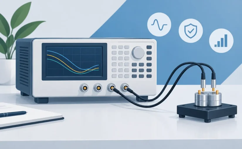
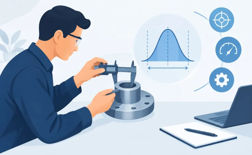
A 10 nH inductor, a 0.5 pF capacitor, or a milliohm-range impedance can disappear beneath the electrical behavior of the fixture holding it. Correct fixture measurement offsets are therefore not a cosmetic instrument setting. They are the correction that separates the component under test from the leads, contacts, adapters, and geometry used to reach it.

For production screening, failure analysis, incoming inspection, and precision rework, an offset error can create false rejects, mask damaged parts, or make two operators obtain different answers from the same component. The smaller the DUT value relative to fixture parasitics, the more disciplined the compensation process must be.

Why correct fixture measurement offsets matter

Every fixture adds impedance. Fixture conductors contribute series resistance and inductance. Open terminals, insulating surfaces, and adjacent conductors contribute shunt capacitance and leakage. At higher test frequencies, even a few millimeters of conductive path can become a meaningful portion of the measured impedance.

An LCR meter measures the total network present at its measurement terminals. Without correction, the displayed value includes the DUT plus the fixture’s residual electrical effects. A capacitor may read high because of parallel stray capacitance. A low-inductance component may read high because of lead and contact inductance. A low-resistance part may appear to have greater ESR because probe contact resistance is included in the result.

The practical question is not whether a fixture needs compensation. It is whether its residuals are significant compared with the required measurement uncertainty. A 100 uF electrolytic capacitor measured at a modest frequency may tolerate a simple compensated clip lead setup. A 0.2 pF RF capacitor or 5 nH inductor requires a far more controlled connection, short current paths, stable positioning, and verification against suitable standards.

The fixture model behind offset correction

Fixture correction generally addresses two different error paths: a series path and a parallel path. Understanding both prevents a common mistake: applying one correction and assuming every parasitic has been removed.

Open correction removes parallel residuals

With the fixture open and no DUT installed, the meter measures the residual admittance between the test terminals. This is usually dominated by stray capacitance and insulation leakage. The instrument uses that result to subtract the fixture’s parallel contribution from subsequent measurements.

Open correction is especially relevant for low-capacitance work. A few tenths of a picofarad from a socket, test board, or poorly spaced clip lead can be larger than the DUT itself. Keep the fixture in its normal measurement position during the open routine. Moving leads afterward changes the electric field and invalidates the captured offset.

Short correction removes series residuals

With the fixture terminals shorted at the DUT connection plane, the meter measures series resistance and inductance associated with leads, contacts, and conductor layout. The instrument then removes this series impedance from the measurement.

The short must be low impedance and physically representative. A long wire placed across the ends of a fixture is not an ideal short at 100 kHz or 250 kHz. It adds inductance and may introduce a correction that is worse than no correction. Use a wide, short, clean conductive short at the same location where the DUT terminals normally sit.

Load verification checks whether compensation is believable

Open and short routines correct a model. They do not prove that the model matches every DUT. Verification with a known, stable component or calibrated standard confirms that the corrected setup produces acceptable results at the selected frequency, test level, and measurement function.

This step matters when a fixture has spring contacts, a clamping mechanism, a relay matrix, or interchangeable adapters. Mechanical variation can change contact resistance and lead geometry. If verification shifts after several insertions, investigate the fixture before changing instrument settings.

Set the measurement conditions before capturing offsets

Offsets belong to a specific measurement configuration. Capture them only after selecting the test frequency, equivalent circuit, test signal level, and measurement mode used for the work. Changing conditions afterward can make a previously valid compensation unsuitable.

Frequency is the most obvious dependency. Inductance and capacitance parasitics have frequency-dependent reactance, while dielectric loss, skin effect, and contact behavior may also change. A fixture compensated for a 1 kHz capacitance measurement should not automatically be trusted for a 100 kHz ESR measurement.

Test level can also matter. Some components are voltage-sensitive, and some fixtures include contacts whose resistance improves or degrades with current. For semiconductor junctions, magnetic components, and high-value ceramic capacitors with DC-bias effects, define the measurement condition first and treat offset correction as part of that documented method.

Equivalent circuit selection deserves the same discipline. Series and parallel models can produce very different displayed values when dissipation factor or quality factor is low. Select the model appropriate to the component’s expected behavior at the test frequency, then capture the offsets for that method. Compensation cannot correct an unsuitable measurement model.

A controlled procedure for correct fixture measurement offsets

Start by inspecting the complete measurement path. This includes the meter terminals, Kelvin connectors, tweezers or probes, adapters, fixture contacts, and any test board. Oxidation, flux residue, loose fasteners, damaged insulation, and unstable probe pressure create errors that no stored offset can reliably remove.

Allow the instrument and fixture to stabilize at the operating temperature when the work requires tight limits. Copper resistance, contact pressure, and insulation leakage can shift as a fixture warms. In a production environment, this is one reason to perform a quick verification check at the beginning of a shift and after a fixture change.

Set the intended frequency, signal level, bias condition if used, range behavior, and series or parallel function. Then perform the open correction with the fixture arranged exactly as it will be used. Keep operators’ hands away from sensitive open terminals during sub-pF work. Body capacitance can easily alter the reading.

Next, install the proper short at the DUT plane and perform the short correction. For Kelvin fixtures, preserve the force and sense geometry used in actual testing. A short placed upstream of the contact points does not correct the contact resistance and inductance downstream of that location.

Remove the short, install a verification standard, and record the measured result. Compare it with the standard’s value and allowable uncertainty at the test frequency. If the result is outside tolerance, do not repeatedly rerun correction hoping for a better number. Check the fixture, shorting method, contacts, cable routing, and selected measurement parameters.

For repeatable production work, document the correction procedure with enough detail that another technician can reproduce it. Include the fixture identification, meter model, connector type, frequency, test level, equivalent circuit, correction date, verification component, and acceptable limits. This converts a one-time adjustment into a controlled measurement process.

Fixture design choices that reduce the need for correction

Compensation is most effective when the fixture is already electrically disciplined. It is not a substitute for good fixture design. Keep the DUT connection plane close to the measurement terminals, minimize loop area, separate high and low conductors appropriately, and avoid unnecessary adapters.

For low resistance and low inductance, four-terminal Kelvin connections are often essential. Separating current force from voltage sense minimizes the effect of lead and contact resistance on the sensed DUT voltage. However, Kelvin connections do not eliminate inductance created by a large current loop. The physical layout still controls high-frequency performance.

For low-capacitance work, use short, rigid connections and stable insulating materials with low leakage. A fixture that changes shape when a lid closes, a probe is pressed, or a cable is moved can change its capacitance enough to compromise sub-pF measurements. Guarding may be appropriate in specialized high-impedance applications, but it must be designed around the instrument’s measurement architecture rather than added casually.

Direct-contact instruments can reduce the fixture path substantially for small SMD components. Smart Tweezers® are particularly useful when the goal is fast component identification or in-circuit comparison with minimal lead length. Even then, clean tips, consistent contact pressure, and a zeroing routine remain necessary when measuring near the lower limits of capacitance, inductance, or resistance.

When offsets should be repeated

Repeat correction whenever the electrical or mechanical measurement path changes. That includes changing adapters, replacing probes, repositioning cables, cleaning or replacing contacts, moving from one fixture insert to another, or changing frequency and test mode. A dropped fixture or a newly tightened screw can be enough to justify verification.

Time is another factor. A stored correction may remain suitable for a stable, enclosed fixture, but high-throughput sockets and spring probes wear. Humidity, contamination, and thermal cycling also change leakage and contact behavior. The right interval depends on the required uncertainty and process risk, not on a universal calendar rule.

Treat an offset as a measurement asset with a defined scope. When that scope changes, recapture it. This habit keeps the instrument reading tied to the DUT rather than to the unexamined behavior of the fixture around it.

The fastest route to dependable low-value measurements is not more averaging or a more impressive display resolution. It is a fixture whose residuals are understood, corrected at the DUT plane, and verified under the same conditions used to make the pass or fail decision.

Best Instruments for Incoming Inspection

A reel can carry the correct manufacturer label, date code, and package marking yet still contain parts that are out of tolerance, moisture-damaged, mixed, or electrically defective. The best instruments for incoming inspection turn that uncertainty into documented measurement evidence before components enter production, repair inventory, or a high-reliability build.

For electronic components, incoming inspection is not a single test. It is a measurement strategy that compares the component delivered against the approved part specification, the purchase requirement, and the limits that matter to the finished circuit. The right toolset depends on whether the risk is value drift, polarity error, counterfeit substitution, physical damage, solderability, or lot-to-lot variation.

Start With the Incoming Inspection Risk

A receiving team does not need to measure every parameter on every component. That approach is slow, expensive, and often fails to detect the defect most likely to disrupt assembly. Instead, define a control plan by component type, supplier history, application criticality, and the cost of a production escape.

Commodity resistors may only require package verification and resistance sampling. A low-ESR capacitor used in a power rail deserves capacitance and ESR checks at a relevant test frequency. RF inductors, precision capacitors, high-voltage diodes, and components used in aerospace, medical, or defense assemblies may require tighter sampling, traceable calibration, and more complete recordkeeping.

The critical question is not simply, “Does this part measure?” It is, “Can this instrument measure the required parameter at the required value, frequency, accuracy, and fixture condition?” A 10 nH inductor, for example, cannot be evaluated confidently with a general-purpose meter whose lead inductance exceeds the device under test.

Best Instruments for Incoming Inspection of Electronics

No single instrument covers every incoming-inspection task. A capable station combines fast screening tools with higher-resolution instruments for components where parasitics, test frequency, or tight tolerances determine the pass/fail decision.

Precision handheld LCR meters and Smart Tweezers

For passive-component receiving, a precision LCR meter is often the highest-value instrument on the bench. It measures inductance, capacitance, and resistance while also providing secondary parameters such as ESR, dissipation factor, quality factor, impedance, and phase angle, depending on the model and test setup.

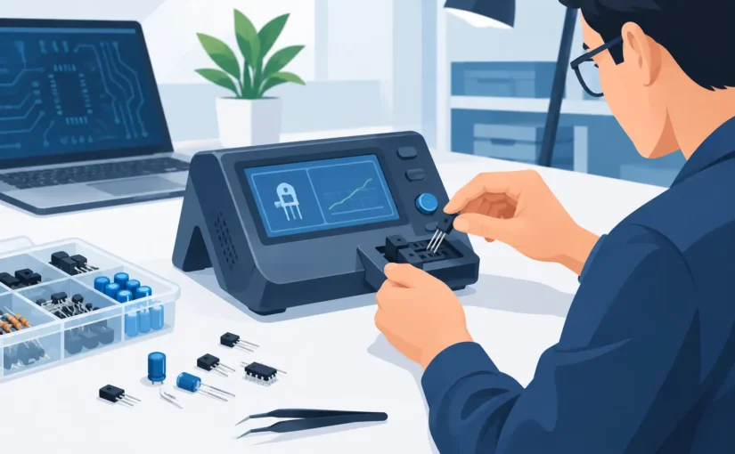
Direct-contact tweezer instruments are particularly effective for small SMD parts. The operator can pick a 0402 capacitor, resistor, or inductor directly from a sample strip and obtain an automatic component identification and value reading without attaching clips or building a fixture. This reduces handling time and avoids the unstable lead contact that can corrupt low-value measurements.

Test frequency matters. A capacitor that appears acceptable at a low test frequency may not meet its expected impedance behavior at the frequency relevant to the circuit. Similarly, inductors and ferrites can show substantially different results as frequency changes. Instruments capable of test frequencies up to 250 kHz and measurement ranges extending from sub-1 pF capacitance to 1 F, and from sub-10 nH inductance upward, provide meaningful coverage for modern SMT inventory.

For incoming screening of tiny components, LCR-Reader instruments combine bench-grade measurement capability with portable, direct-contact testing. The practical benefit is speed: inspectors can separate questionable samples from approved inventory before reels are released to the line.

Bench LCR meters and impedance analyzers

A bench LCR meter is the better choice when the incoming specification calls for controlled test conditions, four-terminal fixtures, programmable limits, or sustained high-volume inspection. These instruments are well suited to lot acceptance testing of precision capacitors, inductors, magnetic components, and components with narrow tolerance bands.

An impedance analyzer is justified when frequency response itself is the acceptance criterion. This applies to RF inductors, resonant devices, filters, ferrites, and certain specialty capacitors. It costs more and requires more setup discipline, but it can expose resonance, abnormal loss, and frequency-dependent behavior that a single-frequency LCR test will miss.

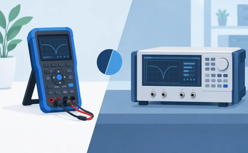
The trade-off is workflow. A bench system offers repeatability and formal test control, while a portable LCR instrument can deliver much faster component-level triage at receiving, on the production floor, or in a failure-analysis area. Many organizations need both: handheld screening for speed and bench verification for critical or disputed lots.

Precision digital multimeters

A high-accuracy digital multimeter remains essential, although it should not be treated as a replacement for an LCR meter. Use it to verify resistance, continuity, DC voltage behavior, diode forward voltage, insulation-related checks where applicable, and basic electrical condition.

For incoming inspection, look for stable low-ohms performance, appropriate resolution, known input characteristics, and calibration documentation. Four-wire resistance measurement is valuable for low-resistance shunts, current-sense resistors, connectors, relays, and cable assemblies because it removes the influence of test-lead resistance.

A multimeter is also the right first-line tool for modules and assemblies. It can identify shorts across supply rails, reversed protection devices, open circuits, and incorrect resistance networks quickly. For component characterization, however, use a meter designed to measure the parameter that actually controls performance.

ESR meters and diode or LED testers

ESR testing is particularly useful when receiving electrolytic, polymer, and some tantalum capacitors. Capacitance alone can appear normal while elevated ESR produces heat, ripple failure, poor transient response, or startup problems in a finished product. Measure ESR under conditions consistent with the component class and the engineering requirement rather than accepting a generic reading as proof of quality.

Dedicated diode and LED testers speed polarity and forward-voltage checks on incoming semiconductors. This is practical for verifying mixed bins, checking marked and unmarked LEDs, and screening components that may have suffered handling damage. A forward-voltage result is a screening measurement, not a full semiconductor qualification, but it can catch an incorrect device before it reaches placement.

Digital microscopes and visual inspection systems

Electrical measurement cannot identify every defect. A digital microscope or high-quality inspection camera reveals cracked MLCCs, bent leads, damaged terminations, poor plating, marking inconsistencies, package contamination, and evidence of prior use or rework.

Magnification should match the package sizes being received. For fine-pitch ICs and small passive components, inspectors need enough optical resolution to evaluate termination condition without introducing interpretation errors from excessive magnification. Consistent lighting is just as important as magnification because it makes surface cracks, scratches, and plating defects easier to distinguish.

X-ray, XRF, and advanced authentication tools

These instruments are not necessary for every receiving dock, but they are appropriate when counterfeit risk, material composition, or hidden internal damage is a credible concern. X-ray systems can inspect internal structure, bond-wire configuration, die placement, voiding, and concealed package damage. X-ray fluorescence, or XRF, can help verify plating or material composition.

The limitation is that advanced inspection tools require trained interpretation and a clear acceptance standard. An unusual image is not automatically a reject. Use these methods for targeted supplier qualification, suspect lots, high-value ICs, and applications where a field failure carries disproportionate cost.

Control Parasitics Before Trusting the Result

Incoming inspection measurements can be wrong even when the instrument is functioning correctly. Test leads, probe pressure, operator contact, fixture capacitance, lead inductance, and component orientation all influence readings, especially at low capacitance and low inductance values.

Use short connections, Kelvin contacts where low resistance is involved, and appropriate open/short compensation for the fixture. For SMD sampling, repeat a measurement on several parts and watch for both average value and spread. A consistent shift across the lot may indicate a legitimate alternate construction, an incorrect component, or a test-condition mismatch. A wide spread may indicate mixed inventory, damage, or inadequate contact.

Document the test frequency, equivalent circuit mode, compensation state, temperature when relevant, and acceptance limits. A capacitance value without its test conditions is often insufficient for a defensible quality record.

Build a Repeatable Receiving Workflow

The strongest incoming-inspection programs combine measurement with traceability. Record the purchase order, manufacturer part number, lot or date code, sample size, instrument identification, calibration status, operator, measured values, and disposition. Bluetooth-enabled data recording can reduce transcription errors and make lot-level evidence easier to review.

Calibration should be traceable to recognized standards and aligned with the organization’s quality system. A calibrated instrument does not eliminate method error, but it establishes confidence that the instrument is performing within specification. Check verification standards or calibration boards routinely, especially after transport, heavy use, or a questionable result.

Set acceptance limits from the component datasheet and internal engineering requirements, not from assumptions about nominal values. A 1% resistor, for instance, should be evaluated against the approved tolerance and test method, while an MLCC may require consideration of DC bias, temperature coefficient, and frequency-dependent behavior before a receiving result is interpreted.

The most useful instrument is the one that produces a repeatable decision quickly enough to protect production. Start with the components most likely to create expensive escapes, measure them under controlled conditions, and make every pass/fail result traceable to a method your engineering team can defend.

Component Measurement Uncertainty Guide for Engineers

A 10 nH inductor, a 0.5 pF capacitor, or a 10 mOhm resistor can appear to be out of tolerance long before the component itself is the problem. This component measurement uncertainty guide addresses the measurement system around the part: instrument accuracy, resolution, test frequency, contact resistance, fixture parasitics, calibration, and operator technique. For component evaluation, the displayed value is only useful when its uncertainty is small enough to support a real engineering decision.

Measurement uncertainty is not instrument accuracy

Instrument accuracy is one contributor to uncertainty, not the entire result. A specification such as ±0.1% may describe performance under defined conditions, often after calibration and within a stated frequency, range, and temperature window. It does not automatically account for probe contact, stray inductance, open-circuit capacitance, component orientation, or the repeatability of a handheld measurement.

Measurement uncertainty expresses the expected interval around a reported result. If a capacitor is measured at 100.0 pF with an expanded uncertainty of ±1.2 pF, the defensible result is not simply 100.0 pF. It is 100.0 pF ±1.2 pF at the stated test conditions and confidence level.

That distinction matters during incoming inspection, failure analysis, and production screening. A 5% capacitor tolerance may tolerate a modest uncertainty budget. A 1% resistor, a low-ESR polymer capacitor, or an RF inductor close to a design limit may not.

Start with the parameter and test conditions

A component does not have one universal value. Resistance varies with test current and temperature. Capacitance and dissipation factor vary with frequency, DC bias, temperature, and dielectric behavior. Inductance can shift with frequency, current, core condition, and the parasitic capacitance of the part and fixture.

Before calculating uncertainty, define what is being measured. Record the primary parameter, equivalent model, test frequency, test signal level, and any DC bias. For an LCR measurement, specify whether the instrument is reporting series or parallel values, such as Cs-D, Cp-D, Ls-Rs, or Lp-Rp.

A 10 uF ceramic capacitor measured at 1 kHz with no DC bias is not necessarily equivalent to the same part in a 12 V power rail. Likewise, a 1 uH inductor tested at 100 kHz may produce a different result at 250 kHz as it approaches self-resonant behavior. The uncertainty statement must apply to the stated measurement condition, not a generic component label.

Build an uncertainty budget around the real setup

A useful uncertainty budget identifies each meaningful source, estimates its magnitude, and combines the contributions. The objective is not paperwork for its own sake. It reveals which error source is controlling the result and whether a better instrument, a different fixture, or improved process discipline will make the measurement more reliable.

For most component measurements, assess these contributors:

  • Instrument accuracy at the selected range, frequency, and parameter
  • Display resolution and quantization
  • Calibration standard uncertainty and calibration interval drift
  • Repeatability from repositioning the component or changing contact pressure
  • Probe, lead, and fixture parasitics
  • Open, short, load, or fixture compensation residuals
  • Ambient temperature and component self-heating
  • Test-frequency and test-level variation
  • Operator setup and equivalent-circuit selection

Not every term deserves equal weight. A 1% uncertainty from lead resistance can dominate a 1 mOhm resistance measurement, while display resolution may be irrelevant. At 0.5 pF, however, residual open capacitance, shielding, humidity, and proximity to the operator can be larger than the component under test.

Separate repeatability from systematic effects

Repeatability is typically evaluated with repeated readings. Measure the same component several times, removing and replacing it if that reflects normal workflow. The standard deviation of those results is a Type A uncertainty estimate. If readings shift when the part is rotated or the tweezers are repositioned, the contact method is part of the uncertainty budget.

Systematic effects are estimated from specifications, calibration certificates, compensation residuals, known fixture behavior, and engineering judgment. These are commonly treated as Type B contributions. They include the instrument accuracy limit, reference-standard uncertainty, and residual error after open-short compensation.

Avoid the common shortcut of taking the largest specification and calling it total uncertainty. Independent contributors are normally combined by root-sum-square:

`u_c = √(u₁² + u₂² + u₃² + …)`

The combined standard uncertainty, `u_c`, is often expanded using a coverage factor of approximately 2 for about 95% confidence:

`U = k × u_c`, where `k = 2` is commonly used when appropriate.

The statistical assumptions matter. When a formal ISO/IEC 17025 result is required, the laboratory should document distributions, degrees of freedom, correlation, and the selected coverage factor. For engineering verification, a disciplined working budget is often sufficient, provided it is conservative and repeatable.

Control contact and parasitic effects first

At low impedance, contact resistance and lead inductance can overwhelm the component. Two-wire resistance methods include lead and contact resistance in the result. Four-wire Kelvin measurement separates force and sense paths, substantially reducing this error for low-resistance devices, shunts, traces, and connectors.

At low capacitance, every exposed conductor becomes part of the measurement circuit. Test leads, clips, fingers, bench surfaces, and even movement near the measurement point can add measurable capacitance. Keep connections short, use compensated fixtures, minimize unshielded metal, and perform open compensation with the fixture arranged exactly as it will be used for testing.

At low inductance, lead geometry is equally critical. A long loop adds inductance, and a component placed in a different location can produce a different result. Direct-contact tweezer measurements reduce lead length and support fast SMD evaluation, but probe spacing, jaw cleanliness, and component placement still require control.

Compensation is not a one-time ritual. Repeat open and short compensation when the test frequency changes, when leads or Kelvin connectors are replaced, when fixture geometry changes, or when the environment changes enough to affect sub-picofarad work. A compensation routine removes predictable setup effects. It does not correct unstable contacts or a damaged probe tip.

Match frequency and model to the component behavior

Selecting the wrong test frequency can create a measurement that is precise but irrelevant. Electrolytic capacitors are often evaluated at frequencies that reveal ESR behavior. Small ceramic capacitors may require high-frequency testing to resolve low values and characterize RF-relevant behavior. Inductors require a frequency well below self-resonance if the goal is nominal inductance rather than resonant behavior.

The equivalent model matters as much as frequency. A low-loss capacitor may be represented effectively by a parallel model in one range, while a higher-loss capacitor measured near its operating region may require a series model. The same principle applies to inductors with substantial winding resistance or core loss.

Do not compare results from different models as if they were interchangeable. Report the result as, for example, `Cs = 99.8 pF, D = 0.0012 at 100 kHz`, not merely `99.8 pF.` This gives another engineer enough information to reproduce the measurement and determine whether it is meaningful for the application.

Use calibration evidence correctly

Traceable calibration establishes that an instrument was compared against standards with a documented chain of measurement traceability. It does not guarantee every field result is accurate. Calibration confirms instrument performance at specified points, under controlled conditions, at a point in time.

Review the calibration certificate for the parameter ranges and frequencies that matter to your work. An instrument may be calibrated for capacitance, resistance, and inductance across multiple ranges, but the uncertainty assigned at 1 kHz may not apply at 100 kHz or 250 kHz. Between calibrations, use verification artifacts or calibrated boards to detect damage, drift, or compensation problems before they affect production decisions.

Portable precision instruments, including LCR-Reader models configured with Kelvin probes or direct-contact tweezers, can deliver bench-grade utility in the field only when the operator preserves the measurement conditions behind the specification. Clean contacts, valid compensation, controlled frequency, and periodic verification are what translate a data-sheet accuracy claim into a dependable result.

Turn uncertainty into pass-fail decisions

A measured value near a specification limit requires guardbanding. Suppose a 100 pF component has a tolerance of ±5%, creating limits of 95 pF to 105 pF. If the expanded measurement uncertainty is ±1 pF, accepting a measured value of 95.1 pF risks accepting a part whose true value is below the lower limit.

A simple guardband approach moves the acceptance limits inward by the applicable uncertainty. In this case, an acceptance region of 96 pF to 104 pF reduces false acceptance risk. The exact rule depends on the cost of a false accept versus a false reject, contractual requirements, and the required confidence level. Aerospace or medical production may demand a more formal decision rule than a repair bench screening process.

For troubleshooting, uncertainty may serve a different purpose. If two nominally identical capacitors measure 18% apart while the total uncertainty is 2%, the difference is actionable. If they differ by 0.3% with a 1% uncertainty, further conclusions are not supported by the measurement.

Document the result so it can be repeated

A practical test record should identify the component, measured parameter, equivalent model, frequency, test level, fixture or probe method, compensation status, temperature if relevant, instrument identification, calibration status, result, and expanded uncertainty. For a high-volume workflow, this can be integrated into a data-logging process. For repair work, a concise bench record may be enough.

The most valuable uncertainty budget is the one that changes how you test. If contact repeatability is dominant, improve the contact method. If residual fixture capacitance dominates, shorten and shield the fixture. If the instrument term dominates, select a range or frequency with lower specified uncertainty. A component result becomes defensible when the measurement system has been engineered with the same care as the circuit under test.

Precision Impedance Tester Specifications That Matter

A 10 nH inductor, a 0.5 pF capacitor, and a low-ESR ceramic capacitor can all produce misleading results when the instrument, fixture, and test conditions are not matched. Precision impedance tester specifications are therefore more than a catalog checklist. They define whether a measurement is usable for failure analysis, incoming inspection, board rework, or component characterization.

For engineers and technicians working with SMD devices, the central question is not simply, “What range does the meter display?” It is whether the tester can resolve the value at the required test frequency, maintain stated accuracy under realistic conditions, and control the parasitics introduced by probes, leads, contacts, and the operator’s workflow.

Precision impedance tester specifications: start with the measurement task

An impedance tester measures the opposition a component presents to an AC test signal. Depending on the selected model, it may report resistance, capacitance, inductance, impedance magnitude, phase angle, dissipation factor, quality factor, equivalent series resistance, or combinations of those parameters.

The correct specification set depends on the device under test. A repair technician sorting 10 uF capacitors may prioritize ESR and automatic component identification. A PCB designer evaluating a 0402 capacitor near its operating frequency needs stable low-capacitance resolution and a known test frequency. A manufacturing engineer verifying inductors needs repeatable readings, fast test cycles, and a calibration process that supports traceability.

This distinction matters because a wide measurement range alone does not establish measurement quality. A tester that reads from picofarads to farads still must provide adequate resolution, accuracy, and repeatability at the specific value and frequency being evaluated.

Accuracy is a system specification, not a headline number

Basic accuracy is usually the first figure buyers compare. A 0.1% basic accuracy specification is meaningful, but it is not a universal error limit for every component, range, and test frequency. It commonly applies under defined conditions, often near a reference range and after proper calibration.

Read the accuracy statement as an equation, not a marketing label. Instruments may specify error as a percentage of reading plus a number of counts, or as a percentage of reading plus a fixed offset. At very small capacitance and inductance values, the offset term and fixture parasitics can become more significant than the nominal component value.

For example, a few tenths of a picofarad from probe spacing, contamination, or a nearby grounded surface can materially affect a sub-1 pF measurement. Similarly, a few nanohenries of lead inductance can overwhelm the value of a low-inductance device. In these applications, the tester’s native resolution is only part of the answer. Contact geometry, open/short compensation, shielding, and measurement technique determine whether that resolution becomes reliable data.

Repeatability should be considered alongside accuracy. If a production operator measures the same part ten times, readings should remain within the process tolerance needed for a pass/fail decision. A highly accurate instrument that requires slow, delicate setup may be appropriate for a laboratory bench, yet unsuitable for fast incoming inspection. Conversely, a handheld instrument that provides repeatable direct-contact readings can reduce operator variation substantially when small components must be checked one by one.

Calibration and traceability support defensible results

Calibration confirms performance against known standards at defined conditions. For quality systems, repair documentation, aerospace work, and controlled manufacturing processes, ask whether the instrument can be supplied with a calibration certificate and whether the reference standards are traceable to recognized national standards.

Calibration does not remove the need for daily verification. A practical workflow includes checking the tester with known components or a calibration board before a critical measurement session. That check can reveal damaged probes, contaminated contacts, depleted batteries, or an incorrect compensation state before suspect parts are rejected unnecessarily.

Test frequency determines what the result means

A capacitor or inductor is not a fixed value under all AC conditions. Capacitance changes with dielectric behavior, DC bias, temperature, and frequency. Inductors are affected by core material, winding resistance, and self-resonance. ESR is especially frequency-dependent.

For that reason, test frequency is one of the most consequential precision impedance tester specifications. A device measured at 100 Hz may produce a valid result that has little relevance to a circuit operating at 100 kHz. A tester offering multiple frequencies, extending to 250 kHz where required, gives the user a closer view of component behavior in its intended application.

Higher frequency is not automatically better. At sufficiently high frequency, fixtures and leads contribute enough inductance and capacitance to distort results, and a component may approach resonance. The useful choice is the frequency that matches the design requirement, component data sheet conditions, or established inspection procedure.

When comparing instruments, verify which parameters are available at each frequency. Some instruments offer a broad frequency range but limit accuracy, available modes, or test signal level at the highest settings. The operating manual should make those boundaries clear.

Range, resolution, and low-value capability are different claims

Range describes the span of values an instrument can measure. Resolution describes the smallest displayed increment. Low-value capability describes whether the instrument can produce useful, repeatable results near the lower end of the range.

These are often confused. A meter may display 0.1 pF increments yet be unable to distinguish a 0.5 pF component from fixture capacitance with acceptable confidence. Likewise, a meter may show nanohenry-level inductance while its leads add far more inductance than the part under test.

For miniature SMD work, seek specifications that address the actual lower limits: sub-1 pF capacitance measurement, sub-10 nH inductance capability, and compensation methods designed for the measurement connection. Instruments such as LCR-Reader Smart Tweezers® are designed around direct-contact measurement, which reduces the uncontrolled lead length that makes tiny-component testing difficult.

At the upper end, confirm that the tester handles the values used in your work without forcing an unsuitable measurement condition. A broad capacitance range, potentially extending to 1 F, is useful for screening large electrolytics and supercapacitors. But a high-capacitance reading does not replace an ESR measurement when diagnosing a capacitor in a switching power supply.

Connection method controls parasitic error

The connection is part of the instrument. Two-wire leads are convenient and often sufficient for general measurements, but their resistance and inductance become part of the result. Kelvin connections separate current sourcing from voltage sensing, reducing errors caused by lead and contact resistance. They are particularly valuable for low-resistance and low-ESR measurements.

For loose 0201, 0402, and similar SMD components, tweezer-style probes offer a different advantage: direct contact at the component terminals. This can speed sorting and troubleshooting while avoiding long clip leads. The trade-off is that probe cleanliness, jaw pressure, part orientation, and operator handling still matter. A contaminated tweezer tip can create more uncertainty than the instrument’s published basic accuracy.

Open and short compensation should be easy to perform and appropriate to the selected fixture. Open compensation addresses stray capacitance and leakage paths. Short compensation addresses residual resistance and inductance. Repeating compensation after changing probes, cables, frequency, or the physical setup is good measurement practice, not an optional refinement.

Test signal level and equivalent circuit models affect component behavior

Test voltage and test current can change the answer. Ferrite inductors may respond differently as excitation level increases. Some ceramic capacitors exhibit voltage-dependent capacitance. Semiconductor junctions and protection devices may need controlled stimulus to avoid misinterpretation.

Review whether the tester lets you select or identify the test level. If the component’s data sheet specifies capacitance at a particular AC voltage and frequency, measure as close to those conditions as practical. A result obtained at a much lower signal level may still be useful for sorting, but it should not be treated as a direct substitute for the data sheet value.

Also check the equivalent circuit model. Series and parallel models describe loss differently. Low-impedance capacitors and inductors are often evaluated with a series model, while high-impedance components may be better represented by a parallel model. Automatic model selection improves speed, but the operator should understand which model is being reported when results are compared with specifications or historical data.

Data handling and speed matter in professional workflows

A standalone reading is enough for occasional troubleshooting. Production and validation work often require more. Bluetooth data logging, stored measurements, remote recording, and exportable results help document lot screening, establish trends, and support corrective-action investigations.

Speed is equally practical. Automatic component identification can reduce button presses when operators move between resistors, capacitors, and inductors. Fast settling time matters when hundreds of parts must be inspected, but excessive speed without stable contact can create false failures. The best workflow balances cycle time with a clearly defined measurement dwell time and acceptance limit.

Before selecting an instrument, write down the smallest and largest values you measure, required frequencies, acceptable uncertainty, connection type, calibration requirements, and documentation needs. That short specification will reveal whether you need a portable direct-contact tester, a Kelvin-connected instrument, or a full bench setup. The right tester is the one that turns a tiny component into a measurement you can trust and act on.

Impedance Analyzer Review for Precision Work

A useful impedance analyzer review starts where component failures actually occur: at the test point. A capacitor that reads correctly at 1 kHz may show unacceptable ESR at its operating frequency. A low-value inductor can be dominated by fixture inductance before the instrument reports a meaningful result. And a 0201 resistor cannot be evaluated efficiently if the probe connection contributes more uncertainty than the part itself.

For engineers, technicians, and quality teams, the right instrument is not simply the one with the widest advertised range. It is the one that produces repeatable, defensible measurements at the values, frequencies, and connection geometry that matter to the job. That requires evaluating impedance measurement capability as a complete system: analyzer, measurement model, test frequency, fixture, calibration method, and data workflow.

What an Impedance Analyzer Must Measure

Impedance is a complex quantity with both magnitude and phase. A serious analyzer must do more than display a nominal resistance, capacitance, or inductance value. It must resolve how the device under test behaves as frequency changes and report the parameter model appropriate to that behavior.

For a component under test, the most useful reported values commonly include impedance magnitude, phase angle, resistance, reactance, capacitance, inductance, dissipation factor, quality factor, ESR, and conductance. The correct parameter is application-dependent. A ceramic capacitor may be screened by capacitance and dissipation factor, while a switching inductor may require inductance, Q, and series resistance at a frequency close to its operating range.

This distinction matters because equivalent circuits change with frequency. At lower frequencies, a capacitor often behaves like a capacitance with series resistance. Near self-resonance, lead and internal inductance become significant. Above resonance, the same part behaves inductively. An analyzer that presents one value without clear test conditions can create a false sense of certainty.

Impedance Analyzer Review Criteria That Affect Results

Published specifications are useful only when they are read in context. The following criteria determine whether an instrument can support component evaluation, incoming inspection, failure analysis, or production troubleshooting.

Test frequency and frequency resolution

Frequency range is usually the first specification engineers compare, and it should be. Test frequency must overlap the electrical behavior of the component and the application. Measurements at 100 Hz or 1 kHz may be appropriate for bulk electrolytic capacitors, while high-frequency ceramic capacitors, RF inductors, and very small parasitic values need substantially higher test frequencies.

Range alone is not enough. Review the available fixed frequencies, sweep capability, frequency accuracy, and resolution. A broad sweep helps identify resonance, transition points, and abnormal frequency response. A handheld LCR instrument with selectable frequencies can be a better production or service tool when the task is rapid verification at one or two defined conditions rather than full characterization.

For portable work, test frequencies up to 250 kHz can be highly practical for evaluating small capacitors, inductors, and SMD components outside a conventional laboratory setup. The correct choice depends on whether the work requires a frequency-response curve or fast, controlled measurement at a known operating point.

Basic accuracy versus real measurement uncertainty

A basic accuracy figure such as 0.1% is meaningful, but it is not the same as uncertainty across every range and frequency. An engineering review should examine the accuracy tables for the actual parameter, value range, test level, and frequency being used. Resistance accuracy does not automatically describe capacitance accuracy at the lower end of a capacitance range.

Also consider repeatability. In manufacturing and repair, a stable reading that repeatedly identifies a deviation from a known-good part can be more operationally valuable than a broad specification that cannot be reproduced at the probe tips. This is especially true for screening parts, establishing pass/fail limits, and comparing production lots.

Traceable calibration supports confidence in those decisions. Calibration records, documented procedures, and known standards provide the measurement chain needed when results affect quality systems, customer returns, or regulated hardware.

Low-value measurement capability

The difficult measurements reveal an instrument’s real design quality. Sub-1 pF capacitance, sub-10 nH inductance, and low milliohm resistance measurements are easily distorted by cables, test fixtures, contact resistance, and nearby conductive surfaces.

For low capacitance, stray capacitance in the fixture can exceed the device under test. For low inductance, the physical loop created by the test leads contributes inductance that may be larger than the component value. A device can claim an impressive measurement range yet be unsuitable for these applications if its connection method cannot control parasitic effects.

Direct-contact tweezer measurement has a major practical advantage for small SMD components. By keeping the current path short and placing the measurement contacts directly on the component terminations, it reduces lead-related uncertainty and eliminates time-consuming clip placement. Smart Tweezers® instruments are particularly suited to rapid loose-component identification, board-level troubleshooting, and sorting small parts where conventional lead fixtures are inefficient.

Fixture design, Kelvin connections, and compensation

No impedance analyzer is independent of its fixture. Two-wire connections are often adequate for higher-value measurements, but they include lead and contact resistance in the result. Four-wire Kelvin connections separate source and sense paths, improving low-resistance measurement and reducing error caused by leads.

Open, short, and load compensation are equally important. An open correction characterizes stray admittance in the fixture. A short correction characterizes residual series impedance. A load correction can improve performance against a known reference standard. These corrections should be performed with the same cables, probes, adapters, and physical arrangement used for the measurement.

A common mistake is to compensate a fixture once, then add an adapter or reposition the leads. At low values and higher frequencies, that change can invalidate the correction. The fixture is part of the instrument system, not an accessory to ignore.

Choosing Between a Bench Analyzer and a Portable LCR Instrument

A bench impedance analyzer is the right choice when the work requires detailed sweeps, controlled bias conditions, automated characterization, research-grade fixture options, or documentation of impedance behavior across a wide frequency range. It is also appropriate when samples must be tested under tightly defined voltage, current, temperature, or DC bias conditions.

A portable precision LCR meter is often the stronger choice when the decision must be made at the component, board, receiving dock, repair station, or field-service location. The primary advantage is not convenience alone. It is faster access to a valid measurement with less handling, less fixture setup, and fewer opportunities for probe-placement error.

For example, a technician identifying unmarked SMD components does not necessarily need a frequency sweep. Automatic component identification, direct contact, selectable test conditions, and stable readings can reduce a multistep bench process to a few seconds. In this case, portability directly improves throughput and can prevent incorrect replacement of a component during repair.

The trade-off is straightforward. Portable instruments generally do not replace a full laboratory analyzer for every frequency-domain investigation. Conversely, a bench instrument is not automatically the most efficient tool for 500 rapid checks of loose 0402 capacitors. Purchase decisions should follow the workflow, not the largest specification headline.

Data Logging and Measurement Documentation

A reading that cannot be retained, compared, or traced may have limited value in quality and engineering work. Bluetooth-enabled data recording can support incoming inspection, lot comparison, process troubleshooting, and maintenance documentation without forcing the technician to transcribe measurements by hand.

Logging is especially useful when a failure is intermittent or when multiple components must be compared against a known-good assembly. Record the test frequency, equivalent-circuit mode, compensation state, measurement range, and fixture used alongside the value. A capacitance number without those conditions is incomplete measurement data.

For production use, establish acceptance limits from measured known-good samples rather than relying only on nominal component markings. This accounts for tolerance, process variation, and the specific test configuration. It also gives quality teams a practical basis for detecting drift before it becomes a field failure.

Questions to Ask Before Selecting an Instrument

The most productive evaluation questions are specific. What is the smallest capacitance, inductance, or resistance value that must be measured? At what frequency must the result be valid? Will components be measured loose, on boards, or in a custom fixture? Is a four-wire Kelvin connection required? Must measurements be logged, calibrated, or included in a customer-facing report?

Also ask whether the device under test can be safely measured in circuit. Passive-component readings on populated boards can be affected by parallel paths, semiconductor junctions, and energized circuitry. In-circuit measurement is useful for troubleshooting, but it is not a substitute for understanding the surrounding circuit. When the result matters, isolate one terminal or compare against an identical known-good board.

The best instrument choice is the one that makes the required measurement credible at the point of work. Define the component values, frequency conditions, fixture geometry, and documentation requirements first. Then select the analyzer or portable meter that controls the error sources your application cannot tolerate.

Portable Circuit Diagnostics Guide for Field Work

A failed board in the field rarely arrives with a schematic, a known-good comparison unit, and unlimited time. The portable circuit diagnostics guide that works in this setting is not a collection of isolated meter functions. It is a measurement sequence that identifies the failure boundary, controls parasitic effects, and produces results another technician can repeat.

Portable diagnostics should reduce uncertainty, not simply move bench habits into a smaller case. A handheld instrument is valuable when it can make a defensible decision at the point of service: whether a supply rail is shorted, whether an SMD capacitor has changed value, whether an inductor has developed excessive loss, or whether a suspect component must be removed for confirmation.

What Portable Circuit Diagnostics Must Accomplish

A practical field workflow begins by separating four questions that are often confused: Is power present? Is the signal path active? Is the component value plausible? Is the observed value actually caused by the component under test?

A digital multimeter answers the first question efficiently. It establishes voltage, continuity, resistance, diode junction behavior, and gross current conditions. It does not, by itself, characterize the loss of a multilayer ceramic capacitor, the inductance of a low-value power inductor, or the equivalent series resistance of an electrolytic capacitor. Those conditions require an LCR or ESR measurement with a known test frequency and measurement model.

Portability also has a metrology requirement. A compact instrument must retain sufficient resolution, accuracy, and calibration control for the values being measured. Reading a 0.5 pF change with a device whose fixture capacitance or probe movement introduces several picofarads is not diagnostic work. It is noise presented as a number.

Portable Circuit Diagnostics Guide: Use a Controlled Sequence

The fastest troubleshooting process is staged. Begin with broad observations, then increase measurement specificity only when the evidence justifies it. This avoids removing components prematurely and prevents a single misleading in-circuit reading from driving the repair.

1. Stabilize the board and establish the failure condition

Record the board identifier, revision, reported symptom, supply requirements, and environmental condition. Intermittent behavior caused by heat, vibration, humidity, or load should be reproduced before components are tested. A board that passes at room temperature with no load may still fail in its actual operating condition.

Inspect the assembly under magnification before touching a probe. Look for cracked MLCCs, lifted pads, discolored resistors, fractured solder joints, contaminated connectors, and polarity errors. Visual inspection does not replace measurement, but it determines where high-value measurements should begin.

Then verify that the board is safe to test. De-energize it before resistance, capacitance, inductance, ESR, or semiconductor checks. Discharge bulk capacitors and confirm that stored energy has been removed. An energized rail can damage a precision handheld meter, corrupt the result, or create a hazard for the operator.

2. Check power distribution before testing individual parts

Measure rail-to-ground resistance and compare it with a known-good board when available. A very low resistance reading is not automatically a fault. Core rails, high-current logic rails, and circuits with many parallel IC decoupling capacitors can present low resistance by design.

The diagnostic value comes from comparison and context. If one rail is substantially lower than comparable boards, localize the short by section, connector, or removable load. Use current-limited power injection only when the procedure is approved for the assembly and the likely failure mechanism supports it. Thermal methods can reveal a shorted component quickly, but they can also stress sensitive devices if current limits are poorly chosen.

3. Characterize suspect passive components at the right frequency

Component values are frequency-dependent in real circuits. Capacitance, inductance, dissipation factor, quality factor, and ESR can all change as the test frequency changes. A nominal value measured at one frequency may appear acceptable while the component fails at its application frequency.

For capacitors, measure capacitance and loss together when possible. A capacitor can remain near its nominal capacitance yet have ESR high enough to destabilize a switching regulator or degrade ripple filtering. For inductors, evaluate inductance and series resistance or quality factor. A damaged winding, cracked core, or overheated termination may not produce an open circuit, but it can alter loss characteristics enough to cause converter or RF performance failures.

Very small SMD components demand short measurement paths. Direct-contact tweezer measurement minimizes lead inductance and fixture capacitance relative to clip leads, especially when measuring sub-1 pF capacitance or low-nanohenry inductance. LCR-Reader Smart Tweezers® instruments are designed for this kind of direct component contact, automatic identification, and portable precision measurement.

4. Decide whether an in-circuit reading is trustworthy

In-circuit testing is efficient because the component can remain on the board, but the circuit around it always matters. Parallel resistors lower measured resistance. Parallel capacitors raise measured capacitance. Semiconductor junctions, IC protection structures, and alternate signal paths can make a good component appear defective.

Use the schematic, board layout, and a known-good comparison to judge whether the surrounding network is likely to influence the result. If a measured value is clearly outside tolerance and the topology supports the finding, an in-circuit decision may be sufficient. If the reading is close to a limit or inconsistent with the failure symptom, isolate one terminal or remove the component for confirmation.

This is a trade-off, not a universal rule. Removing a 0201 capacitor may create rework risk, while leaving it in circuit may mask a subtle fault. The correct choice depends on component accessibility, board value, available spares, and the confidence required before disposition.

Control Parasitics Before Calling a Part Bad

At low values, the fixture can dominate the measurement. Probe separation, dirty tips, cable movement, operator handling, and nearby conductive surfaces can all influence pF- and nH-level readings. Zeroing and calibration compensation should be performed with the same probes, connectors, and measurement geometry used for the test.

Keep contacts clean and apply consistent pressure. Oxidation at a component termination can look like high resistance or unstable ESR. A handheld instrument with Kelvin-capable connections is particularly useful where lead and contact resistance would otherwise overwhelm a low-resistance measurement.

For production, repair, or quality-control work, use a calibrated reference artifact or calibration board to verify instrument behavior at relevant values. Traceable calibration supports confidence in the meter, but it does not eliminate the need for correct test setup. Measurement uncertainty includes the instrument, the fixture, the environment, and the circuit itself.

Use Signature Behavior When a Value Is Not Enough

Some failures cannot be reduced to a single resistance, capacitance, or diode reading. Analog signature analysis can compare the current-voltage behavior of a node or component against a known-good signature. This is useful for identifying leaky semiconductors, degraded junctions, abnormal clamping behavior, and circuit sections that look normal under static resistance testing.

Signature results are most useful when the test conditions are consistent. Compare the same node, polarity, range, and test stimulus. A difference may reveal the faulty area, but interpretation still requires circuit knowledge. For example, a differing signature on a logic rail can result from a failed IC, a damaged bypass network, or simply a different board state.

Preserve Evidence, Not Just a Pass or Fail

A portable instrument becomes more valuable when its readings enter the repair record. Record the measurement mode, test frequency, range, board state, probe configuration, and ambient conditions when relevant. For borderline results, include the accepted tolerance and the reference value from a known-good assembly.

Bluetooth-enabled logging is useful when measurements must be documented across multiple boards, shifts, or field locations. It reduces transcription errors and makes trends visible, such as a capacitor lot that shows increasing ESR or a connector family with recurring contact resistance issues. Data logging does not replace judgment, but it turns isolated troubleshooting into actionable quality evidence.

Select Instruments by the Failure Modes You Expect

A field kit should be built around the assemblies being serviced. For general power and control boards, a high-quality DMM, portable LCR/ESR meter, direct-contact tweezers, Kelvin connections, and appropriate calibration references cover a broad set of component-level decisions. For RF, sensor, and dense digital assemblies, prioritize low-capacitance and low-inductance capability, stable test frequency options, and fixtures that do not add uncontrolled parasitics.

Do not select solely by the widest published range. Basic accuracy, resolution at the values you actually measure, test frequencies, repeatability, contact method, and calibration support determine whether an instrument will shorten diagnostics or create more retest work. Bench-grade performance in a portable format matters most when the result decides whether a board is repaired, rejected, or returned to service.

The best field measurement is the one that narrows the fault with enough confidence to guide the next action. Treat every reading as evidence with conditions attached, and portable diagnostics becomes a controlled engineering process rather than a search for a convenient number.

Surface Mount Component Inspection Guide

A 0201 capacitor can look perfectly placed and still be the source of an intermittent rail, failed calibration, or rejected board. This surface mount component inspection guide focuses on the decisions that matter after visual acceptance: determining whether the correct part is present, whether it is electrically sound, and whether the measurement itself can be trusted.

Surface-mount inspection is not a single test. It is a controlled sequence that starts with workmanship and ends with documented electrical evidence. The required depth depends on the application. A consumer assembly may need fast process screening, while avionics, medical, aerospace, and production-failure analysis demand traceable methods, controlled test conditions, and defensible limits.

Start With Inspection Intent and Acceptance Limits

Before probing a component, define the question being asked. Is the objective to catch placement defects at incoming inspection, isolate a board-level fault, verify a reel of inventory, or qualify a substitute component? Each objective calls for different evidence.

A visual inspection can confirm package marking, orientation, solder-joint coverage, polarity, tombstoning, cracked bodies, and lifted terminations. It cannot confirm capacitance, ESR, leakage, dielectric behavior, inductance, or a resistor value that has drifted under stress. Conversely, an in-circuit resistance reading may be misleading when parallel current paths are present. Good inspection avoids treating any one indication as a final verdict.

Set acceptance limits from the component datasheet, approved vendor specification, assembly drawing, and circuit function. Nominal value alone is insufficient. A 10 uF MLCC may be within its marked tolerance at a low test voltage yet provide far less effective capacitance under DC bias. A 100 ohm resistor may read correctly while an adjacent solder bridge changes the circuit behavior. The limit must match the failure mechanism being screened.

Build a Surface Mount Component Inspection Workflow

A repeatable workflow reduces both false rejects and missed defects. The sequence below is appropriate for most bench, repair, and production-support work.

  1. Verify the reference designator and approved value. Compare the bill of materials, schematic, placement data, and package size before making a measurement. Similar-looking 0402 capacitors and resistors are easy to interchange.
  2. Inspect the package and solder joints under magnification. Look for rotation, polarity errors, insufficient wetting, voiding, cracks, chipped terminations, solder balls, bridges, and evidence of rework heat.
  3. Check for circuit-level symptoms. Measure for shorts to ground, abnormal rail resistance, missing bias, or unexpected voltage before assuming the mounted component is defective.
  4. Measure with a method suited to the component and circuit. Use direct-contact probes or tweezer contacts for discrete parts. Remove or isolate the component when parallel paths, active semiconductors, or stored charge make the in-circuit result ambiguous.
  5. Record the value, test frequency, test condition, and disposition. A value without a frequency, range, and measurement location is often not useful for later comparison.

The order matters. Measuring first and examining later wastes time when the actual problem is a cracked termination, incorrect orientation, or a component placed at the wrong reference location.

Visual Defects That Merit Electrical Follow-Up

Visual inspection is fastest when it is targeted. MLCC cracks commonly originate at the board edge, near mounting holes, beside connectors, or under mechanically stressed assemblies. A crack may be nearly invisible from above but can create intermittent leakage or a short after thermal cycling. Inspect component sidewalls and terminations at multiple angles, especially after depanelization or connector insertion.

For resistors, look for darkening, fractured protective coating, shifted end caps, and evidence of overload. For diodes, LEDs, tantalum capacitors, and polarized electrolytics, confirm cathode or positive-mark orientation against the PCB polarity marking. For inductors and ferrite beads, check for fractured cores, displaced shields, and inadequate solder fillets that add unstable contact resistance.

Automated optical inspection is valuable for placement and solder appearance, but it has limits. It may not identify a wrong capacitance value in an unmarked ceramic package, latent MLCC cracking, or a component that passes geometry rules but fails electrically. X-ray inspection can expose hidden voiding and bottom-terminated package issues, yet it also does not replace electrical characterization.

Measure Small Values Without Measuring the Fixture

At surface-mount scale, fixturing and handling can dominate the reading. A few millimeters of probe spacing, contaminated tips, finger proximity, or poorly controlled contact pressure can add enough parasitic capacitance or inductance to obscure the component under test. This is most severe below 10 pF and below tens of nanohenries.

Use clean, sharp contacts and keep the current path short. For low-resistance measurements, Kelvin techniques separate the force and sense paths so lead and contact resistance do not become part of the result. For small capacitors and inductors, perform open and short compensation with the actual probe geometry whenever the instrument supports it. Compensation is not a cosmetic adjustment. It establishes the reference plane at the contact tips and removes predictable fixture effects.

Direct-contact tweezer instruments are particularly effective for loose SMD parts because they minimize lead length and allow rapid measurement without clips or adapters. A precision handheld instrument such as Smart Tweezers can automatically identify common passive components while providing L, C, R, and ESR data at the point of contact. That capability speeds sorting and troubleshooting, but the technician still must select a test frequency and range appropriate to the part and its specification.

Match Test Frequency to the Failure You Need to See

Capacitance and inductance are frequency-dependent quantities. A measured value is meaningful only when the test frequency, equivalent circuit model, and signal conditions are understood.

A low-frequency reading may be useful for high-value capacitors or general sorting. Higher test frequencies provide better discrimination for small capacitors, low inductances, and high-frequency bypass components, but they can also expose effects that are normal for the technology. An MLCC near its self-resonant frequency will not behave as an ideal capacitor. A ferrite bead should not be evaluated as though its nominal impedance were a simple DC inductance.

ESR is equally conditional. A capacitor with acceptable capacitance can have elevated ESR that compromises ripple filtering or regulator stability. Measure at a frequency relevant to the circuit and compare against a known-good part or vendor data when available. For inductors, assess DC resistance as well as inductance. A winding or termination fault can increase DCR while leaving a superficial inductance check inconclusive.

Know When In-Circuit Measurements Are Valid

In-circuit measurement is efficient, but it is not automatically authoritative. Resistors in parallel read low. Capacitors connected across a power rail may include the total rail capacitance, semiconductor junction effects, and charge from other devices. Inductors may be coupled to nearby circuits. Semiconductor protection structures can cause an LCR meter to identify behavior that does not represent the target component.

Begin with an in-circuit reading when it can quickly reveal a hard short, open part, grossly incorrect value, or mismatch against an identical channel. Then isolate one terminal or remove the component when the circuit topology prevents a clear result. Desoldering introduces its own risks, including pad damage and thermal stress, so do not remove a part merely because the first reading differs from nominal. First determine whether parallel paths explain the deviation.

Comparison testing is often more powerful than absolute testing. On a multichannel board, measure the same reference position on a known-good channel using identical probe placement and settings. A meaningful difference can direct further analysis even when neither in-circuit reading equals the datasheet value.

Document Results So They Survive Handoff

An inspection record should identify the board revision, reference designator, component description, instrument model, calibration status, probe or fixture method, test frequency, measured values, ambient conditions when relevant, and final disposition. A photo of the defect location is useful when solder-joint condition or orientation is part of the finding.

For repeated work, create a controlled inspection sheet with expected ranges and test setups. This turns troubleshooting knowledge into a reproducible process and prevents two technicians from reaching different conclusions with different frequencies, probe methods, or acceptance assumptions. Bluetooth-enabled measurement logging can further reduce transcription errors where data capture is required.

The most useful inspection result is not simply “pass” or “fail.” It is a result that states what was measured, under what conditions, and why that evidence supports the disposition. When tiny components are tested with controlled contacts, appropriate frequency, and clear circuit context, inspection becomes a faster path to reliable repair and repeatable manufacturing decisions.

Component Tester Review for Professional Engineers

A component tester review should begin at the point of failure, not with the display size or the number of advertised functions. When a 0402 capacitor reads unexpectedly low, a power inductor shows excess loss, or incoming parts need fast verification, the real question is whether the instrument can produce a repeatable measurement under the conditions that matter. A tester that identifies a component correctly but cannot control parasitics, test frequency, or contact quality may slow down an engineering workflow rather than improve it.

Component Tester Review: Measure the Work, Not the Spec Sheet

A general-purpose component tester is useful for sorting through loose parts, checking polarity, and identifying common semiconductors. For professional component evaluation, however, automatic identification is only the starting point. Engineers and technicians need meaningful L, C, R, ESR, dissipation factor, quality factor, impedance, and phase measurements at conditions relevant to the circuit.

That distinction becomes critical with surface-mount devices. A nominal 10 pF capacitor, for example, can be strongly affected by probe capacitance, fixture geometry, contamination, and the operator’s handling technique. At the other end of the range, a low-value inductor can be dominated by lead and contact inductance. A useful instrument must account for the measurement path instead of treating every component as though it were a through-hole resistor on a clean test fixture.

Review specifications in the context of the expected components and failure modes. A wide measurement range is valuable, but only if it is supported by suitable resolution, stated accuracy, and repeatable test conditions. For repair work, ESR and semiconductor checks may deserve priority. For component engineering, incoming inspection, and laboratory use, test frequency, low-value capability, calibration method, and data documentation usually carry more weight.

Accuracy needs a stated test condition

Basic accuracy is often presented as a single headline number. It is useful only when paired with the range, frequency, equivalent circuit model, and calibration state. A 0.1% basic accuracy specification can be meaningful for precision work, but the applied uncertainty changes with impedance, component value, test leads, and environmental conditions.

Look for an instrument that clearly identifies its operating limits rather than implying that one accuracy figure applies everywhere. For capacitance below 1 pF and inductance below 10 nH, fixture and probe effects can exceed the value being measured. Open, short, and load compensation are not optional refinements in this range. They are part of the measurement.

Test Frequency Determines Whether the Result Is Useful

A component tester may measure a capacitor accurately enough at a low test frequency yet miss behavior that matters in a switching regulator, RF section, or high-speed interface. Similarly, an inductor’s apparent inductance and loss can change substantially as test frequency rises. A component tester review should therefore identify both the available frequencies and how easily the operator can select or verify them.

Low-frequency measurements are often appropriate for large electrolytic capacitors, relays, and general resistance checks. Higher frequencies become more informative when assessing small ceramic capacitors, ferrites, RF inductors, and components used in fast power conversion. An instrument capable of testing up to 250 kHz provides a more relevant view of many modern passive components than a fixed low-frequency meter.

Frequency alone does not establish measurement quality. The selected equivalent circuit matters as well. Series and parallel models are mathematical representations of a component’s behavior at a given frequency and impedance. Using a series model for a low-loss, high-impedance capacitor or a parallel model for a low-impedance inductor can produce values that are technically valid but operationally misleading. The best instruments make model selection visible and provide enough information for the user to understand what is being reported.

Probe Design Is a Performance Feature

For loose SMD components, direct-contact tweezer probes can remove several unnecessary steps. The operator does not have to place a 0201 or 0402 part into a fixture, stabilize it with clips, and then compensate for long leads. The contact path is short, the part can be measured where it is handled, and the result is available in seconds.

That convenience only matters when the probes are mechanically stable and electrically appropriate. Fine tips must reach small pads and component terminations without shorting adjacent conductors. The measurement system must also minimize the capacitance and inductance introduced by the probe assembly itself. Direct-contact measurement is particularly valuable for sorting reels, diagnosing boards, and confirming removed components, but in-circuit use still requires judgment. Parallel paths, semiconductor junctions, and energized circuitry can invalidate the result or damage the instrument.

For larger components, Kelvin connections are often the better choice. Separating source and sense paths reduces the influence of lead and contact resistance, which is essential when evaluating low-ohm resistors, battery connections, fuse resistance, and high-current conductors. A serious portable tester should support the probe configuration that matches the measurement, not force every task through one connector.

Automatic Identification Is Fast, Not Infallible

Automatic component identification is a major workflow advantage. It accelerates the first pass through unknown inventory and helps technicians distinguish a resistor from a diode, capacitor, or inductive component without changing test modes. It is especially effective when the component is isolated and its value falls within the instrument’s optimized range.

Still, an automatic result should be treated as a test hypothesis, not a final engineering decision. A damaged ceramic capacitor can exhibit leakage or unusual loss. A semiconductor may be influenced by charge stored in the device or by board-level circuitry. Composite networks, thermistors, transformers, and components with nonlinear behavior require interpretation beyond a single automatic label.

The most productive workflow combines automatic identification with immediate access to primary parameters. Once the instrument identifies a capacitor, the operator should be able to assess capacitance, ESR, dissipation factor, and test frequency without navigating through a slow menu structure. Fast testing is not merely about autoranging. It is about reaching a defensible pass-or-fail decision with fewer handling steps.

Calibration, Repeatability, and Traceability

A reading that cannot be repeated is rarely useful for quality control. This is why professional evaluations should separate convenience features from metrology features. Calibration support, documented adjustment procedures, known reference standards, and traceable calibration options determine whether measurements can support production records, inspection decisions, or laboratory documentation.

Portable instruments have an advantage when their calibration process is practical. A calibration board or task-specific verification standard allows users to check instrument response before a critical measurement session. This does not replace formal calibration when a quality system requires traceability, but it helps reveal damaged probes, contamination, drift, or setup errors before they affect a batch of components.

Repeatability also depends on operator technique. Clean probe tips, consistent contact pressure, stable component placement, and appropriate compensation can matter more than an incremental specification advantage. In a component tester review, look for an instrument that makes correct technique easy through clear displays, fast compensation routines, and accessories designed for the intended measurement range.

Data Logging Matters When One Reading Is Not Enough

A handheld meter is often chosen for speed at the bench or in the field. Yet component screening, failure analysis, and production troubleshooting can require a record of what was measured, when, and under which conditions. Bluetooth-enabled logging or export capability can turn a portable tester into a practical data-collection instrument without adding a full bench setup.

Logging is most valuable when it preserves context. A useful record includes the measured parameters, range or frequency, component identifier, and pass/fail criteria where applicable. Collecting a list of values without test conditions can create false confidence, particularly when multiple operators or multiple component lots are involved.

LCR-Reader instruments address this professional requirement by combining direct-contact measurement with high-resolution LCR capability, accessory options for specialized tasks, and calibration-oriented workflows. The right configuration depends on whether the primary work is SMD evaluation, cable and connector verification, incoming inspection, board repair, or documented laboratory measurement.

Selecting the Right Tester for the Job

The best choice is not always the instrument with the longest feature list. A repair technician who mainly checks electrolytic capacitors and diodes may benefit most from speed, durable probes, and clear ESR results. A PCB designer investigating low-value passives needs better control of parasitic effects, test frequency, and equivalent circuit models. Manufacturing teams may prioritize repeatability, accessories, calibration documentation, and data capture over maximum portability.

Before buying, test the expected workflow against the instrument’s actual specifications. Identify the smallest capacitance and inductance values that must be resolved, the frequencies used in the target circuits, the component packages handled most often, and whether results must be recorded. Then assess how compensation, probes, calibration, and data handling support that work. The most useful component tester is the one that makes the next measurement more trustworthy, not merely more convenient.

Handheld Versus Bench LCR Analyzers Compared

A 0402 capacitor that reads correctly in a fixture can still become a questionable result when it is measured with long leads, the wrong test frequency, or insufficient open/short compensation. That is the real decision behind handheld versus bench LCR analyzers: not simply portable versus stationary, but whether the measurement system matches the component, the production pace, and the required confidence level.

For component incoming inspection, failure analysis, PCB rework, field service, and lab characterization, the best instrument is the one that controls the dominant sources of error without adding unnecessary time to every test. A bench analyzer remains the reference choice for many controlled laboratory measurements. Modern handheld instruments, particularly direct-contact tweezer designs, can deliver bench-grade performance for a substantial range of component-level work while eliminating fixture handling and lead parasitics.

Handheld Versus Bench LCR Analyzers: The Core Difference

A bench LCR analyzer is designed around controlled measurement conditions. It typically offers a broad selection of test frequencies and signal levels, extensive equivalent-circuit modes, programmable sweeps, external fixtures, and computer-controlled automation. Its physical size is not a drawback when the device remains in a laboratory, calibration department, or production test station.

A handheld LCR analyzer prioritizes direct access to the part under test. It can move to a populated board, a reel sample, a repair bench, or an incoming-inspection cart. The most capable handheld units reduce setup time by automatically identifying the component type and selecting an appropriate measurement function. In tweezer form, the probes become the fixture, allowing the operator to contact an SMD component directly rather than attaching clips or transferring the part to a test socket.

Neither format is inherently more accurate. Accuracy is a system outcome affected by instrument specifications, test frequency, connection method, calibration state, compensation, component value, and environmental stability. The meaningful comparison is whether each platform can achieve the required uncertainty for the actual test method.

Accuracy Starts at the Contacts

For low-value capacitors and inductors, test leads can dominate the measurement. Lead inductance, stray capacitance, contact resistance, and inconsistent probe pressure can obscure the value being evaluated. A bench analyzer with properly selected Kelvin fixtures and completed open/short/load compensation can control these effects exceptionally well. This is the preferred arrangement when measurements must be repeatable across operators, documented for qualification, or used to characterize components over frequency.

However, a conventional bench setup is only as good as its fixture discipline. Long clip leads attached to a high-performance benchtop instrument do not create a high-performance measurement. They can introduce enough parasitic capacitance and inductance to make a small component result misleading.

Direct-contact handheld tweezers address a different part of the problem. Their short probe path and Kelvin-style measurement geometry reduce the connection distance between the instrument and a small SMD device. This is especially useful for capacitors below 1 pF, inductors below 10 nH, low-resistance devices, and parts that are awkward to hold in a conventional fixture. For technicians sorting mixed inventory or diagnosing a board-level failure, fast, repeatable contact often matters more than a full set of laboratory sweep functions.

The trade-off is operator technique. Probe alignment, stable contact, and clean terminations still matter. A portable instrument should be calibrated and verified just as deliberately as a bench system, particularly when pass/fail limits are tight.

Frequency Determines Whether the Result Is Useful

An LCR value is not fixed in the way a resistor color code suggests. Capacitance, inductance, loss, ESR, dissipation factor, and impedance vary with frequency, bias conditions, and the component’s construction. Measuring a ceramic capacitor at 1 kHz may be appropriate for one specification and irrelevant for another. Measuring an inductor at too low a frequency can conceal behavior that appears in its intended circuit.

Bench analyzers commonly provide the widest frequency range, fine frequency resolution, signal-level control, and programmed sweeps. That capability is necessary for resonant-device characterization, dielectric studies, impedance profiling, component qualification, and engineering investigations where a single test point cannot answer the question.

Handheld instruments are often optimized around a defined set of practical frequencies. That is not a limitation when those frequencies align with the work. A handheld analyzer operating up to 100 kHz or 250 kHz can cover demanding inspection and troubleshooting tasks, including ESR evaluation and high-speed verification of many passive components. The correct question is not whether a device has every possible frequency. It is whether it measures at the frequency required by the component specification or the circuit failure mode.

When comparing specifications, verify the stated accuracy at the intended frequency and measurement range. A basic accuracy figure alone is incomplete. A 0.1% specification has meaning only when accompanied by test conditions, connection method, range, and calibration status.

Throughput Is a Measurement Requirement

At a bench station, the operator may need to select a range, attach a fixture, compensate the setup, place the component, record the result, remove the component, and repeat. That process is appropriate for controlled testing, but it becomes costly when hundreds of small parts must be screened or when a repair technician needs an answer before heat can spread through a board.

Handheld analyzers can materially reduce handling time. Automatic component recognition removes mode selection for many routine checks. Tweezer contacts eliminate the transfer step for loose SMD parts. Bluetooth-enabled data recording can preserve readings without forcing the operator to manually transcribe values. These advantages are operational, not cosmetic: fewer handling steps mean fewer opportunities for incorrect range selection, swapped test leads, and undocumented measurements.

Bench systems retain the advantage where throughput depends on automation rather than individual operator speed. A programmed test sequence, feeder, switching matrix, or production fixture can test parts with consistent contact force and predefined limits. For high-volume qualification or automated quality control, that repeatability may outweigh the cost and footprint of the bench infrastructure.

When a Bench Analyzer Is the Better Choice

A bench LCR analyzer is generally the right choice when the measurement requires broad frequency sweeps, controlled AC drive levels, DC bias, complex fixture arrangements, automated test control, or formal component characterization. It is also the stronger platform when test methods are locked to a customer, military, aerospace, or internal quality procedure that specifies the instrument configuration and calibration workflow.

Laboratories evaluating dielectric behavior, transformer parameters, resonant networks, or impedance across a frequency range need the analytical depth of a bench platform. The same applies when engineering teams must correlate results across multiple sites using identical fixtures and procedures.

This does not mean a bench analyzer should be the default for every engineering department. A high-capability instrument sitting unused because it takes too long to set up does not improve quality. The test process must fit the decision being made.

When a Handheld Analyzer Produces the Better Workflow

A handheld LCR analyzer is the better operational choice when the component cannot conveniently come to the instrument, when SMD values must be verified quickly, or when technicians need to isolate suspect components without building a fixture for each task. Repair specialists can compare a known-good board location with a suspected failure point. Incoming inspectors can spot-check capacitors, inductors, resistors, and diodes before inventory reaches production. Field teams can confirm replacement parts without carrying a benchtop instrument into the service environment.

Portable capability is particularly valuable when parasitic effects are the concern. Direct-contact measurement reduces the lead length that can distort very small capacitance and inductance values. It also allows measurement close to the physical point of interest, which is often more relevant than taking a component to another room and measuring it under a different connection geometry.

LCR-Reader instruments are designed around this use case: portable direct-contact measurement with professional accuracy, high-frequency capability, and calibration-supported workflows for component-level decisions.

Select by Measurement Risk, Not Instrument Category

The practical purchase decision should begin with the component population and the consequence of a wrong result. If the work centers on SMD passives, rework verification, inventory sorting, field diagnosis, and rapid failure isolation, a precision handheld analyzer can provide the fastest route to a defensible result. Evaluate its basic accuracy, usable frequency range, minimum measurable capacitance and inductance, Kelvin contact design, logging capability, and calibration options.

If the work requires parameter sweeps, bias control, formal automation, specialized fixtures, or laboratory-grade characterization across a broad operating range, select a bench analyzer and budget for the complete measurement system, including fixtures, standards, compensation procedures, and operator training.

Many engineering organizations need both. The bench analyzer establishes detailed characterization and supports controlled procedures. The handheld instrument moves that measurement discipline to the production floor, repair station, incoming dock, and field site. The most productive setup is the one that lets qualified personnel make a correct component decision at the point where the decision is needed.

How to Measure SMD Resistor Tolerance Correctly

A 10 kΩ SMD resistor marked for 1% tolerance is not automatically acceptable because a handheld meter displays 10.03 kΩ. To measure SMD resistor tolerance correctly, the measured value must be compared with the correct nominal value, under controlled test conditions, with enough measurement accuracy to make the decision meaningful. For high-volume inspection, repair verification, or incoming quality control, that distinction determines whether a component is released, rejected, or investigated.

What SMD resistor tolerance actually means

Tolerance is the permitted deviation from a resistor’s nominal resistance at specified reference conditions, usually 20°C or 25°C. A 10 kΩ, 1% resistor is specified to fall between 9.90 kΩ and 10.10 kΩ. A 5% version may range from 9.50 kΩ to 10.50 kΩ.

The calculation is straightforward:

Tolerance deviation (%) = ((measured resistance – nominal resistance) / nominal resistance) × 100

A reading of 9.94 kΩ on a nominal 10 kΩ resistor produces a deviation of -0.6%. It passes a 1% limit, but it would not pass a 0.5% limit.

That calculation alone does not establish compliance. The instrument’s resistance accuracy, test-contact quality, temperature, and the condition of the part all contribute to the result. When a reading is close to the specification boundary, the uncertainty of the measurement system must be considered before making a pass/fail decision.

Identify the nominal value before testing

Most chip resistors do not print a tolerance code. Their package markings, when present, typically identify only resistance. Three-digit markings use the first two digits as significant figures and the last digit as the multiplier. For example, 103 represents 10 kΩ. Four-digit codes are often used for tighter-tolerance components, so 1001 represents 1.00 kΩ.

However, marking conventions are not universal. EIA-96 codes, unmarked 0201 and 01005 components, resistor arrays, and specialty current-sense parts require a bill of materials, schematic, reel label, or manufacturer data to establish the nominal value and tolerance. Measuring a resistor accurately cannot reveal its original tolerance grade if the nominal specification is unknown. It only reveals its present resistance.

Equipment needed to measure SMD resistor tolerance

A conventional DMM can be sufficient for larger resistors with moderate tolerances, especially when the test leads are short and clean. It becomes less suitable as resistor size decreases, resistance drops into the low-ohm range, or the acceptance limit tightens.

For loose SMD components, direct-contact tweezer instruments reduce handling time and eliminate much of the lead and fixture variability associated with ordinary probes. Automatic component identification is useful when sorting mixed inventory, but the instrument should be set to resistance measurement when a controlled, documented resistor result is required.

Measurement capability should match the decision being made. A 1% resistor should not be evaluated with a meter whose uncertainty consumes most of the 1% tolerance window. For a 10 kΩ part, 1% equals 100 Ω. A meter and contact arrangement with a possible error of several tens of ohms may be acceptable for broad screening, but not for defensible acceptance near either limit.

Low-value resistors require a four-wire Kelvin method. With a 0.10 Ω shunt, even a few milliohms from probe leads, oxidized tips, or contact pressure can produce a large percentage error. Kelvin connections separate the current path from the voltage-sensing path, removing lead resistance from the measured result. Kelvin probe connectors or purpose-built test fixtures are preferable whenever milliohm-level decisions matter.

A controlled procedure to measure SMD resistor tolerance

Begin with the component out of circuit whenever possible. In-circuit measurement can be fast, but parallel paths, semiconductor junctions, capacitors, and other resistors can alter the reading. A measured value that appears out of tolerance may simply reflect the circuit around it.

Inspect the part before contacting it. Check for cracked end terminations, discoloration, solder residue, contamination, lifted pads, and heat damage. A resistor damaged by overload can drift upward, while poor solder connections can create an unstable or elevated apparent resistance. Physical evidence gives the electrical reading context.

Next, verify the test instrument. Allow it to stabilize according to its operating instructions, inspect probe or tweezer tips, and perform the applicable open, short, or reference-standard check. A calibrated instrument supports traceable measurement, but daily verification is still valuable because worn contacts and contaminated fixtures can degrade a good instrument’s practical performance.

Place the component between clean contacts with consistent pressure. For chip resistors, contact the metallized end caps rather than the resistive body. Avoid sliding hard probe points across small terminations, particularly on thin-film precision resistors, where mechanical damage is possible. Wait for the display to stabilize, then record the measured resistance and test conditions if the result will be used for quality documentation.

Calculate the deviation from nominal and compare it with the specified limit. In production, define a guard band when the instrument uncertainty is material relative to the tolerance. For example, a nominal 1.000 kΩ resistor with a ±0.1% component tolerance has a 999.0 Ω to 1001.0 Ω acceptance range. If the complete measurement uncertainty is ±0.2 Ω, a 1000.9 Ω result should not be treated with the same confidence as a 1000.2 Ω result. A quality procedure may classify borderline readings for retest with a higher-accuracy setup rather than issuing an immediate rejection.

Use the correct test current and voltage

Resistance measurement applies current or voltage to the device. This is usually noncritical for ordinary thick-film chip resistors, but it matters for very low-value resistors, high-resistance parts, resistor networks, and components with low power ratings.

Excessive test current can introduce self-heating. The power is calculated as I²R, and heating changes resistance according to the resistor’s temperature coefficient. A 0.1% precision resistor can shift enough during a poorly chosen test to obscure a tight tolerance assessment. Conversely, extremely low test current may make a low-ohm reading more susceptible to noise and contact instability.

For high-value resistors, test voltage can expose leakage across dirty surfaces, fixtures, or humid contamination rather than true resistor behavior. Keep components and contacts clean, and use a measurement method appropriate to the required resistance range.

Temperature can change a passing result

Tolerance and temperature coefficient of resistance, or TCR, are related but different specifications. Tolerance defines the allowed resistance deviation at the reference temperature. TCR defines how much resistance changes with temperature, generally expressed in parts per million per degree Celsius.

Consider a 10 kΩ resistor with 1% tolerance and 100 ppm/°C TCR. A 30°C change from the reference temperature can shift resistance by approximately 0.3%, or 30 Ω. That is still within the 1% initial tolerance band, but it can matter in a tight test limit or precision circuit.

For repeatable inspection, let components reach a stable ambient temperature and avoid measuring immediately after rework, reflow, powered operation, or hot-air repair. Hold the board by its edges when possible. Finger heat is usually insignificant for a broad 5% check, but it is not irrelevant when evaluating low-TCR precision parts.

In-circuit measurements: fast screening, limited certainty

In-circuit resistance measurement is useful for finding open resistors, wrong-value placements, and gross assembly faults. It is not automatically a valid tolerance test. Parallel components almost always lower the apparent resistance, while active circuits may create unstable or misleading readings.

If a circuit reading does not agree with the expected value, review the schematic before removing the resistor. One lifted end is often enough to isolate the part for confirmation, although that approach must follow the repair and rework controls appropriate to the assembly. For dense boards, a portable direct-contact instrument can accelerate this workflow by allowing rapid checks without routing large test leads through the work area.

Common causes of false out-of-tolerance results

Unexpected results are often measurement problems before they are component failures. The most common causes are poor contact on end caps, uncorrected lead resistance, measuring in circuit, an incorrect nominal value, unstable temperature, and insufficient instrument resolution or accuracy.

A second issue is assuming every resistor uses a standard tolerance. Precision thin-film parts may be specified at 0.1% or better, while surge, anti-sulfur, high-voltage, and current-sense resistors have application-specific behavior that must be evaluated against the manufacturer specification. A resistance value may be within initial tolerance but unsuitable because its power handling, pulse history, TCR, or long-term drift no longer meets the circuit requirement.

When tolerance verification is routine, standardize the setup: the same contact method, the same verification standard, the same ambient conditions, and clear acceptance limits. Instruments such as Smart Tweezers® support direct component measurement in workflows where speed and repeatability matter, but the quality of the decision still depends on matching the measurement method to the resistor value and tolerance class.

A resistance reading becomes useful engineering evidence only when it is tied to a known nominal value, a defined test method, and realistic measurement uncertainty. Treat borderline parts as a measurement question first, then use a higher-confidence setup to determine whether they truly belong outside the specified limit.