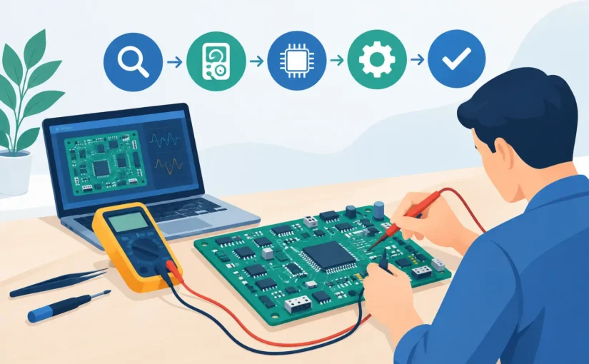
A failed board rarely announces its root cause. A rail may be present but unstable under load. A capacitor may look intact while its ESR has increased enough to disrupt a switching regulator. A populated PCB troubleshooting workflow must therefore move from low-risk observations to targeted, repeatable measurements – not from symptom to random probe placement.
For production, repair, and laboratory work, the objective is not merely to find a bad part. It is to establish evidence: what failed, where the failure is localized, whether the suspected component is actually responsible, and whether the repaired assembly meets its intended electrical behavior. A disciplined sequence reduces rework, protects the board from further damage, and produces data another technician or engineer can verify.
Start the PCB Troubleshooting Workflow Before Applying Power
Begin with the board’s history. Record the reported symptom, serial or revision number, operating conditions, recent modifications, and whether the failure is intermittent, thermal, or load dependent. A board that fails after a reverse-polarity event should be approached differently from one that passes at room temperature but resets after 20 minutes.
Then perform a controlled visual inspection under adequate magnification. Look for damaged packages, cracked MLCCs, lifted pads, missing components, solder bridges, contamination, corrosion, polarized-component orientation errors, and discolored areas around power devices. Check connector pins and mechanical stress points. This stage is fast, but it should not be treated as superficial. Fine-pitch solder defects and fractured ceramic capacitors are frequently visible only under magnification and oblique lighting.
With power removed, compare the assembly to the schematic, bill of materials, known-good board, or assembly image when available. Confirm installed values and package markings where practical. Manufacturing escapes often originate from a correct-looking component placed at the wrong reference designator or a substitute part with inadequate voltage, tolerance, or dielectric characteristics.
Before powering the board, measure input resistance to ground and inspect major supply rails for shorts. A low reading is not automatically a defect. High-current rails, large processor cores, and converter outputs can show low resistance by design. The useful question is whether the reading agrees with a known-good board, the circuit topology, and the expected load path.
Establish a Safe Power-Up Condition
Do not connect an unknown assembly directly to an unrestricted supply. Use a current-limited source set to the expected input voltage and a conservative initial current limit. Observe inrush behavior, steady-state current, and whether the current limit engages. An unexpected current demand can often be localized before damage occurs.
If the board draws excessive current, reduce the applied voltage where the circuit permits and use thermal inspection techniques to locate the active fault area. A component warming rapidly at reduced voltage may indicate a shorted semiconductor, a reversed polarized capacitor, or a low-impedance rail. Thermal behavior is evidence, not proof: some normal regulators, processors, and termination networks dissipate substantial power during operation.
For boards that power normally, verify the power tree before troubleshooting downstream functions. Measure each rail at its source and at the load. Record voltage, ripple, startup sequence, and behavior during the reported fault. A nominal 3.3 V rail measured with a handheld meter may still have enough ripple, dropout, or transient collapse to cause communication failures. Use an oscilloscope when timing, noise, or switching behavior is relevant.
Separate Power Faults From Functional Faults
A practical decision point is whether the board has a power-integrity problem or a functional problem with valid rails. If rail voltage is missing, unstable, sequenced incorrectly, or current-limited, remain in the power section. If rails are within tolerance and stable under the required load, proceed to reset circuits, clocks, references, interfaces, and signal paths.
This separation matters because replacing logic devices before verifying their supply and reference conditions creates false diagnoses. Many apparent IC failures are power delivery failures expressed at the system level.
Measure Components in Circuit With Context
In-circuit measurement accelerates fault isolation, especially on dense surface-mount assemblies, but every reading must be interpreted in the context of parallel paths and semiconductor junctions. A capacitor measured across a rail includes the influence of other capacitors, IC input structures, and the power network. An inductor measurement may include adjacent paths. Resistance readings can change as a meter charges circuit capacitance.
Use direct-contact component measurement to screen accessible parts quickly, particularly when comparing multiple identical channels or a known-good assembly. Smart Tweezers® instruments can automatically identify and measure supported components at the part terminals, making them well suited to checking small SMD resistors, capacitors, and inductors without handling loose parts. For demanding low-value work, measurement setup, probe condition, test frequency, and parasitic compensation determine whether the result is meaningful.
Capacitance alone is not enough for electrolytic and polymer capacitors in many power circuits. ESR, dissipation factor, and measurement frequency can reveal degradation that a simple capacitance measurement misses. Conversely, an MLCC with a reading below its marked value may be affected by DC bias, temperature, or a parallel circuit path rather than physical damage. Remove or isolate one terminal when the in-circuit evidence remains ambiguous.
For resistors, compare measured values against tolerance and the effect of parallel branches. A 10 kOhm resistor that reads 4.7 kOhm in circuit may be perfectly good if it is paralleled by another path. For diodes and transistor junctions, use diode-mode readings in both directions and compare with matched devices where possible. A single reading without circuit context should not trigger replacement.
Use Comparative Measurements to Localize the Fault
The fastest diagnostic reference is often a known-good board of the same revision. Compare input resistance, rail impedance, standby current, startup timing, clock amplitude, reset state, and key component measurements. This approach is especially effective for multi-channel analog boards, repeated converter stages, and assemblies with mirrored circuits.
When no golden unit exists, compare like-for-like circuit blocks on the failed board. If four channels use the same amplifier, regulator, or sensor interface, measure each at equivalent nodes. A deviation in bias voltage, impedance, waveform, or thermal profile narrows the suspect area far faster than scanning the entire design.
Create a small measurement record as you work. Include test point, instrument mode, test conditions, measured value, and expected or comparative value. Bluetooth-enabled data recording can be useful when documenting long test sequences or capturing component populations for quality investigations. The record protects against repeated measurements, supports repair traceability, and exposes patterns across returned boards.
Confirm the Suspect Before Rework
A suspect component should meet more than one criterion whenever possible. It may have an abnormal measured value, an inconsistent thermal signature, a failed comparative test, and a direct connection to the observed symptom. The more independent evidence that agrees, the lower the chance of damaging a board through unnecessary rework.
Before removing a component, inspect the surrounding network and verify that the component’s function matches the diagnosis. A shorted output capacitor may be the failure, or it may be the victim of an overvoltage regulator failure. Replacing only the capacitor in the second case will produce a repeat return.
After rework, inspect pads, vias, nearby passives, and solder joints under magnification. Then repeat the measurement that established the fault, followed by controlled power-up and functional verification. Confirm current consumption, rail behavior, communication, load response, and any environmental or burn-in condition relevant to the original symptom.
Define a Clear Repair Decision
Not every defective board should be repaired. The decision depends on component availability, rework risk, safety requirements, calibration status, and the probability of hidden damage. In aerospace, medical, defense, and controlled manufacturing environments, a board with extensive thermal damage or compromised traceability may require formal disposition rather than field repair.
For repairable assemblies, close the record with the root cause, replaced references, measured before-and-after values, and verification results. If the same failure appears repeatedly, feed that evidence back into design review, incoming inspection, assembly process control, or component qualification.
The most effective troubleshooting practice is measured restraint: apply power only when the evidence supports it, trust comparative data over assumptions, and require a verified post-repair result before returning a board to service.