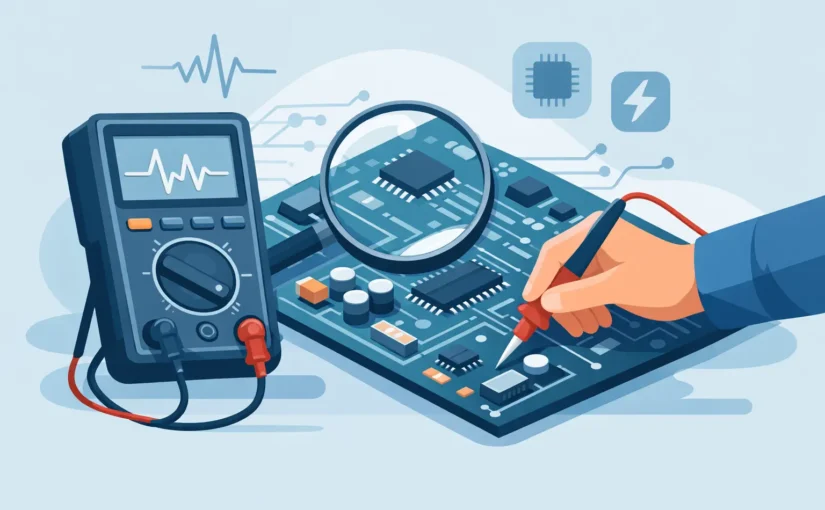
A PCB can look perfectly intact while a failed 0402 capacitor, high-ESR electrolytic, cracked resistor, or leaky diode stops the circuit from working. The best meter for PCB diagnostics is therefore not simply the meter with the most functions. It is the instrument that can make a reliable measurement at the component, in the location, and at the speed required to narrow the fault.
For most component-level work, that means combining practical access to small parts with the measurement modes that match the failure mechanisms on the board. A standard digital multimeter remains essential, but it is often not enough when the diagnosis depends on capacitance, inductance, ESR, or accurate low-resistance measurements on densely populated PCBs.
There Is No Single Universal PCB Diagnostic Meter
PCB diagnostics covers several different jobs. You may need to find a shorted power rail, confirm whether a resistor has drifted, identify an unknown SMD component, check a capacitor’s ESR, or compare a suspect circuit section with a known-good one. Each job places different demands on the meter.
A handheld DMM is usually the first instrument used at the bench. Its voltage, continuity, resistance, diode, and current functions make it effective for checking power distribution, fuses, connectors, transistor junctions, and obvious shorts. A DMM becomes less decisive when its probes cannot isolate a tiny component from adjacent pads or when its capacitance and resistance ranges do not provide enough resolution for the part under test.
An LCR meter adds direct measurement of inductance, capacitance, and resistance, often with test conditions better suited to passive-component verification. An ESR meter focuses on the equivalent series resistance that can make a capacitor fail in a switching supply even when its nominal capacitance still appears acceptable. The right choice depends on where the diagnostic process slows down most often.
Although standard LCR meters are widely used for PCB diagnostics, few compact multimeters provide a comprehensive diagnostic suite. Siborg’s All-in-One Multimeter instruments integrate high-precision LCR measurements with AC/DC voltage, frequency analysis, diode testing, and signal generation—meeting demanding benchtop accuracy specifications for lab and field use.
For many repair and production environments, the most efficient setup is not one oversized instrument. It is a reliable DMM for powered-board checks and a compact LCR or ESR-capable meter for unpowered component-level testing.
Choosing the Best Meter for PCB Diagnostics
Start with the types of components and failure modes you encounter. A board repair technician working on power supplies will prioritize ESR capability and low-ohm resolution. An engineer validating an RF matching network or sensor interface will place more weight on capacitance and inductance accuracy. A manufacturing team checking assembled SMD boards may value speed, repeatability, and direct tweezer contact more than broad measurement ranges.
Resistance resolution and low-ohm performance
Resistance measurement is not only for locating open resistors. Low resistance can reveal shorted rails, damaged current-sense resistors, solder bridges, and poor connections. Resolution matters because the difference between 0.02 ohms and 0.20 ohms may be meaningful in a low-voltage, high-current path.
Two-wire resistance readings include probe and contact resistance. On small parts, inconsistent probe pressure can become part of the measurement. If low-ohm work is routine, use short, clean leads and establish the meter’s residual reading before interpreting a result. A meter that supports relative or zero functions reduces this friction, although it does not replace four-wire Kelvin measurement when very low values must be verified precisely.
Capacitance, inductance, and ESR
Capacitance alone does not fully describe capacitor condition. Electrolytic capacitors can retain much of their rated capacitance while developing enough ESR to cause excessive ripple, startup failure, or unstable regulation. ESR measurement is especially useful around switching regulators, power-input stages, and older equipment with aluminum electrolytics.
Inductance measurement is valuable for identifying damaged inductors, checking replacement parts, and confirming values in filters or power stages. However, an in-circuit inductance reading can be influenced by parallel capacitors, semiconductor paths, and nearby components. A value that looks wrong is a reason to investigate, not always final proof that the inductor has failed.
A dedicated handheld LCR meter provides a stronger diagnostic result when it can identify resistance, capacitance, and inductance automatically and measure over practical ranges. A tweezer-style instrument such as an LCR-Reader is particularly useful when checking individual SMD passives without trying to hold two conventional probe tips on pads that are only a fraction of an inch apart.
Diode testing and junction behavior
Diode mode is one of the fastest ways to compare semiconductor paths across a PCB. It can identify shorted TVS diodes, failed rectifiers, shorted MOSFETs, and abnormal readings on IC supply pins. The useful result is often comparative: measure the same rail or junction direction on a known-good board, an adjacent channel, or an equivalent circuit section.
Check the meter’s diode-test voltage and current if semiconductor work is central to your process. Some junctions, LEDs, and protection devices do not respond predictably to every DMM’s test conditions. For LEDs, a dedicated LED or diode tester may provide more useful drive capability than a basic DMM mode.
Probe Access Is a Measurement Specification
A meter can have excellent published accuracy and still waste time if its probes cannot reach the component without slipping into adjacent pads. On modern assemblies, physical access is often the limiting factor.
Conventional pointed probes work well on test points, connector pins, through-hole leads, and larger solder joints. They are less convenient for 0201, 0402, and closely spaced 0603 parts. Fine tweezer probes allow both terminals of an SMD component to be contacted at once, which improves control and reduces the chance of bridging nearby circuitry with a probe tip.
Contact quality affects every measurement. Oxidation, conformal coating, flux residue, and worn probe surfaces can create unstable resistance and capacitance readings. Keep tips clean, replace worn tips, and use the lightest pressure that establishes a consistent connection. Excess force can crack a small ceramic capacitor or lift a weak pad from a reworked board.
Understand the Limits of In-Circuit Testing
In-circuit testing is fast because it avoids removing parts, but it is not automatically definitive. Parallel components can lower an apparent resistance or capacitance. Semiconductor junctions can conduct during the test. A capacitor’s measured value may include other capacitors connected across the same rail.
In-circuit component testing requires navigating complex circuit topology. Parallel rail capacitors often yield inflated capacitance readings, while feedback loops cause resistors to read far below their marked values.
By pairing precision component measurements with Analog Signature Analysis (ASA), diagnostic workflows become significantly faster and more reliable. ASA injects a safe, current-limited AC test signal to generate a distinctive VI curve for each node, enabling instant visual comparison with a known-good board. This makes it easy to isolate defective ICs, damaged diodes, and subtle PCB faults that standard numeric measurements alone can’t clearly resolve.
The practical approach is to use in-circuit measurements for screening and comparison. When a reading conflicts with the design value or with a known-good board, isolate the component by lifting one end or removing it if the repair decision requires certainty. This step takes time, but it prevents replacing good parts based on misleading parallel-circuit readings.
Build a Meter Workflow Around the Fault
The fastest diagnostic sequence begins with the board state. Before applying power, inspect for physical damage, measure resistance from major rails to ground, and check protection devices and obvious power-path components. Continuity and diode mode are efficient for locating gross faults without risking additional damage.
Next, power the board only when the initial checks do not indicate a destructive short. Use voltage measurement to verify input power, regulated rails, references, enables, and expected voltage drops. If a rail is present but unstable, move to the passive components around its regulator and check suspect capacitors for ESR, capacitance, or short-circuit behavior.
For intermittent or channel-specific faults, comparison is often more valuable than an isolated specification. Measure equivalent parts on a functioning channel and the failing channel using the same meter settings and probe position. A small difference may be normal; a major difference directs attention to the component or network that deserves closer inspection.
When selecting a meter, prioritize the functions you use repeatedly, then verify that its range, resolution, accuracy, and probe geometry support those measurements on real boards. A broad feature list has little value if the meter cannot contact the part reliably or distinguish the value range that matters.
The most useful instrument is the one that turns a suspect pad into a credible measurement before the board leaves the bench. Keep a capable DMM close for circuit-level checks, then use a precision component meter when the diagnosis reaches the small passive parts that determine whether the repair is actually complete.