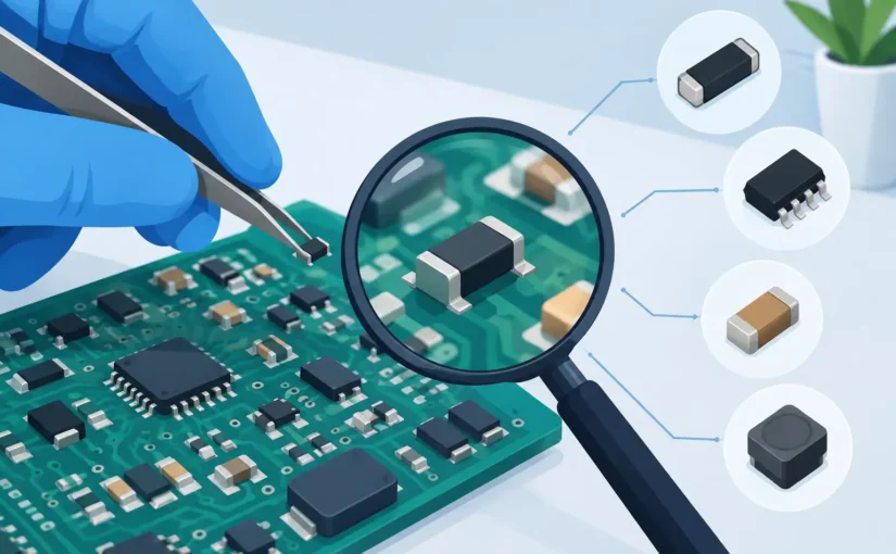
A mixed tray of 0402 and 0603 devices is not an inventory system. Once reel labels, assembly drawings, or board documentation are missing, a visually identical group of chip resistors, MLCCs, ferrite beads, and inductors can quickly become a source of rework, scrap, or latent field failures. To identify unmarked SMD parts reliably, treat the task as a controlled measurement process rather than a visual sorting exercise.
The objective is not merely to obtain a number on a meter. It is to establish component type, nominal value, tolerance band where possible, and whether the part is suitable for its intended circuit position. That requires the right test conditions, an understanding of parasitics, and a clear boundary between what can be measured on a loose part and what must be inferred from the circuit.
Why unmarked SMD components are difficult to identify
Most small passive components carry no readable value code. On parts below 0805, markings are uncommon; on 0402 and 0201 packages, they are effectively absent. Package dimensions may narrow the possibilities, but they do not identify electrical value. A 0603 10 kOhm resistor, 100 nH inductor, 100 nF MLCC, and ferrite bead may look nearly identical from above.
Construction also affects measurements. Multilayer ceramic capacitors can lose capacitance under DC bias. Inductors and ferrite beads are frequency-dependent. Low-value resistors can be dominated by probe and contact resistance. A component measured at the wrong frequency or with unstable contact may appear to be a different part entirely.
There is a second complication: board-level measurements include the circuit connected to the component. Parallel paths lower an apparent resistance, neighboring capacitors increase an apparent capacitance, and semiconductor junctions can alter the reading as test polarity changes. A fast reading is useful for screening, but it is not automatically a valid component identification.
Start with physical and circuit evidence
Before connecting a meter, document what is known. Measure the body length and width with a caliper or compare it against a verified package reference. Record the pad spacing, terminal finish, component color, and any top-side marking. Dark gray or black molded parts often suggest an inductor, bead, or tantalum capacitor, while the familiar beige body of an MLCC is a useful clue, not proof.
Then examine location and circuit function. A small device placed in series with a supply rail is more likely to be a bead, inductor, current-sense resistor, or jumper than a decoupling capacitor. A part connected from a power plane to ground is commonly a capacitor. Repeated footprints around an IC can reveal a decoupling network, while matched pairs close to differential lines may be terminations or common-mode filtering components.
Board reference designators are particularly valuable. R, C, L, FB, D, and Q prefixes do not guarantee that a previous repair was correct, but they establish a strong starting hypothesis. If an intact sister board is available, compare both placement and measured values. This is often more dependable than attempting to identify a part from package appearance alone.
Measure loose components first
A removed component provides the cleanest answer. Test it after it has cooled from hot-air removal and after any flux residue has been cleaned from the terminals. Residue and moisture can matter when evaluating high resistance, low capacitance, or leakage-sensitive parts.
A practical identification sequence has four stages:
- Verify contact quality and compensate for probe resistance, fixture effects, and open/short offsets.
- Use automatic component recognition to establish whether the device behaves primarily as R, L, or C.
- Select a test frequency and range appropriate to the expected value, then record the primary value and dissipation factor, ESR, or quality factor.
- Repeat the measurement after rotating the part or re-seating the contacts to confirm that the result is stable.
Direct-contact tweezer instruments are especially effective for this work because they avoid loose leads and allow the component to be gripped at its terminations. Smart Tweezers® instruments, for example, combine automatic R, L, and C identification with controlled test frequencies and direct-contact measurement for small chip components. For production or laboratory use, repeatability matters as much as speed: a value that shifts every time the probes touch the device is a contact or test-condition problem until proven otherwise.
Identifying chip resistors
For a resistor, begin with a low-resistance-aware measurement method. Standard two-wire probing can add enough lead and contact resistance to distort readings below a few ohms. Kelvin measurement is preferred for current-sense resistors, jumpers, and other low-ohm devices because it separates force and sense paths.
A stable 9.96 kOhm reading strongly supports a 10 kOhm nominal resistor, but it does not establish tolerance without a specification or comparison sample. For high-value resistors, allow the reading to settle. Surface contamination and finger contact can influence megohm-range results.
If a supposed resistor presents substantial reactance, check the test frequency and inspect its circuit role. It may be an inductor, ferrite bead, capacitor, or a resistor network rather than a single chip resistor.
Identifying capacitors
Capacitor measurement requires more caution than a simple capacitance number suggests. MLCCs have broad package overlap, and the value printed by a meter depends on test frequency, AC stimulus, DC bias conditions, temperature, and the capacitor dielectric. A nominal 1 uF X5R capacitor can measure materially below its marked value when biased in service.
For loose parts, measure at a frequency relevant to the expected application and compare against known-good components of the same physical size and likely dielectric family. Very low capacitance values require a clean fixture, short connections, and open compensation. At the sub-picofarad level, stray capacitance from probes, hands, solder residue, and nearby metal can exceed the component under test.
ESR and dissipation factor provide useful secondary evidence. An unexpectedly high loss reading can indicate a damaged capacitor, a poor contact, or a part that is not a capacitor at all. Do not reject an MLCC solely because its measured capacitance differs from a schematic value taken under different bias and frequency conditions.
Identifying inductors and ferrite beads
An inductor’s apparent inductance is frequency-dependent, and a ferrite bead does not behave like an ideal inductor across its working band. A bead may show a small inductance value at low frequency while its intended function is high-frequency impedance and noise suppression. That makes board position and part geometry critical evidence.
For low-value inductors, probe inductance and contact geometry become major error sources. Use short, compensated connections or direct terminal contact, and select an instrument capable of resolving low nanohenry values. Compare the measured inductance and series resistance with known-good devices when available. DC resistance is often helpful for separating a power inductor from a bead, but it cannot identify either part by itself.
Know when in-circuit testing is enough
In-circuit testing is excellent for triage. It can identify a shorted decoupling capacitor, an open series resistor, or a missing inductive path without removing parts. It is less reliable for determining the exact nominal value of a component connected to multiple parallel or active paths.
Use an in-circuit value as a screening result when the surrounding network is understood and the measurement agrees with a known-good board. Remove one terminal, or remove the component completely, when the result affects a repair disposition, incoming inspection decision, or root-cause report. Lifting one end often isolates the component with less risk than full removal, particularly for small passive parts on multilayer boards.
Do not force an RLC classification onto an unmarked diode, transistor, TVS device, or IC. These devices need polarity-aware diode testing, transistor checks, or analog signature analysis. A semiconductor can appear resistive or capacitive to an LCR meter at one stimulus level while behaving very differently under operating conditions.
Build a repeatable identification record
Once a component is identified, preserve the result. Record package size, measured value, test frequency, secondary parameter, instrument model, compensation state, and whether the part was measured loose or in circuit. Add a board location and photo when the work supports repair, quality, or failure analysis.
This record turns a one-time measurement into usable engineering data. It also exposes questionable assumptions. If ten supposedly identical capacitors produce two distinct value clusters, the tray may contain mixed stock. If a value changes only when measured on the board, the circuit is influencing the reading rather than the component itself.
The most useful outcome is not a label placed on one mystery part. It is a measurement method your team can repeat with the same controlled contact, test conditions, and confidence when the next unmarked SMD device reaches the bench.