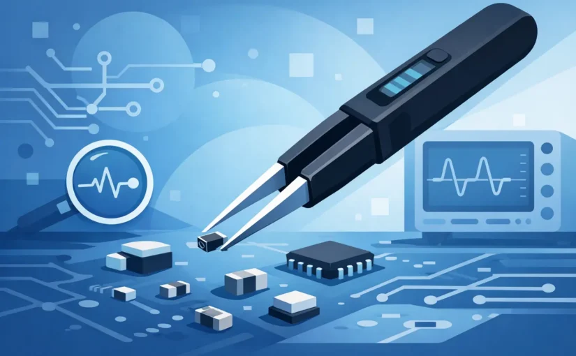
A 0201 capacitor can look perfectly placed, yet be open, cracked, incorrectly loaded, or simply the wrong value. At that scale, the best tweezers for SMD components are not defined only by whether they can pick up a part. They must give the operator controlled mechanical handling and, when troubleshooting or incoming inspection requires it, a dependable electrical connection at the component terminations.
For production placement, rework, failure analysis, and component verification, the right choice depends on the job. Fine hand tweezers excel at placement and alignment. Measurement tweezers add a different capability: direct-contact LCR testing that identifies and characterizes a component without leads, clips, or a large fixture. Treating both tools as interchangeable is a common source of slow work and uncertain results.
What the Best Tweezers for SMD Components Must Do
An SMD tweezer is working against several constraints at once. The tips must reach small terminations without obscuring the work area. Their closing force must be predictable enough to avoid launching a 0402 resistor across the bench or crushing a fragile ceramic capacitor. The body needs enough rigidity that tip alignment remains stable after repeated cycles.
Electrical requirements introduce another layer. Ordinary steel tweezers can hold a component, but they cannot establish a controlled, repeatable test interface. For resistance, capacitance, inductance, and ESR work, each tip must act as an isolated test terminal. The instrument must compensate for its own residual effects and present readings that are meaningful at the value being tested.
This distinction matters most at very low values. A fraction of a picofarad, a few nanohenries, or milliohms of contact resistance can be comparable to the component itself. A tool that is adequate for sorting 10 kΩ resistors may not be adequate for validating a low-inductance RF capacitor or a 1 nH inductor.
Start With the Actual SMD Task
Placement, rework, and visual inspection
For placing components, choose precision hand tweezers with fine, accurately matched tips. Anti-magnetic stainless steel is generally appropriate around magnetic parts and precision assemblies. ESD-safe coatings or conductive materials are preferable where static-sensitive ICs, MOSFETs, and unprotected semiconductors are present.
Tip geometry should follow package size and access. Very sharp tips offer excellent visibility around 0201 and 01005 packages, but they can mark soft terminations and are easier to damage. Fine curved tips improve access under a microscope and reduce wrist angle during rework. Flat or rounded tips distribute force more evenly on larger MLCCs, QFNs, shields, and small mechanical parts.
Mechanical tweezers are the correct tool when the task is physical handling. They should not be selected on the assumption that a good grip also creates a trustworthy electrical test connection.
Component identification and troubleshooting
When answering questions like “What is this part?” or “Is this component still within tolerance?”, smart tweezer meters are the most efficient instrument class. Their integrated tweezer tips contact opposite component terminations directly, enabling rapid LCR measurements without cumbersome test leads. Automatic component recognition instantly identifies resistance, capacitance, or inductance and selects the optimal measurement mode.
Higher test frequencies are critical when measuring miniature capacitors and inductors. While most basic LCR tweezers top out at a 10 kHz test signal—effectively limiting resolution to approximately 10 pF and 100 nH—advanced models like the LCR-Reader R2, R3, MPA, and MPB support test frequencies up to 250 kHz. This extended high-frequency range lowers detection limits down to 0.1 pF and 1 nH similar to professional benchtop meters, making accurate measurement of ultra-small SMD components fast and reliable .
This changes the repair workflow. A technician can lift one end of a suspected component, contact it directly, and compare the reading to the schematic, BOM, known-good board, or component marking. For loose inventory, the same operation quickly separates mixed reels, trays, and salvaged parts without building a dedicated fixture.
In-circuit readings require judgment. Parallel paths can alter the result, semiconductor junctions can affect test behavior, and nearby capacitance or inductance may dominate the measurement. Direct-contact tweezers reduce lead-related parasitics, but they cannot remove circuit topology. When the result is consequential, isolate at least one component terminal.
Quality control and documented measurement
For incoming inspection and controlled production environments, repeatability and traceability matter as much as speed. Look for a defined basic accuracy specification, stated test frequencies, calibration support, and a known method for zeroing or compensating the probes. A display with a stable numeric reading is useful, but it is not evidence of accuracy without these controls.
Data recording can also be decisive. Bluetooth-enabled instruments can transfer readings for inspection records, lot comparisons, and failure-analysis reports without manual transcription. That capability is useful only if the test conditions are controlled: component state, test frequency, test voltage, probe condition, and calibration status should be known.
Tip Geometry Is a Measurement Specification
With ordinary tweezers, tip selection is mostly an ergonomic decision. With measurement tweezers, tip geometry is part of the measurement system. Tips that are too broad may bridge adjacent pads or contact more than the intended termination. Tips that are too sharp may create inconsistent contact pressure, penetrate surface contamination unevenly, or damage delicate electrode finishes.
Fine gold-plated probe tips are often preferred for direct electrical contact because gold resists oxidation and supports reliable low-level connections. The practical goal is not maximum sharpness. It is a repeatable contact patch on the two terminations, with enough visibility to confirm that the probes are not touching adjacent copper, solder fillets, or vias.
Probe spacing deserves the same attention. A narrow gap is essential for tiny chip components, while larger packages may be easier to contact with tips that have a broader working envelope. If a facility regularly handles 01005, 0201, and 0402 parts, evaluate the tool under magnification on representative components rather than relying on a product photo.
Electrical Specifications That Separate Instruments From Handles
A measurement tweezer should be evaluated by the ranges and conditions relevant to the work, not by a generic claim that it “tests components.” The most useful specifications include basic accuracy, resistance range, capacitance range, inductance range, ESR capability, test frequencies, and resolution at the low end of each range.
Frequency is especially significant. Capacitance and inductance are not fixed abstractions independent of test conditions. Ceramic capacitors can exhibit frequency-dependent behavior, inductors have parasitic capacitance and self-resonance, and ESR values change with frequency. A tool operating at higher test frequencies can provide more relevant information for RF, decoupling, and switching-power applications than a low-frequency-only meter.
For extremely small parts, residual compensation is non-negotiable. Open and short calibration routines establish the instrument’s baseline before precision work begins. Perform compensation with clean tips and in the same general configuration used for testing. Recheck it after changing probes, dropping the instrument, or observing unexpected low-value readings.
LCR-Reader® instruments are designed specifically for this direct-contact workflow, combining automatic component identification with precision LCR measurement in a handheld format. Their utility is strongest where bench-meter capability is needed at the board, under a microscope, or at an incoming-inspection station without the delay of lead fixtures.
Siborg also offers dedicated proprietary Open/Short calibration boards, enabling users to null out parasitic capacitance and inductance and extend measurement capability reliably into the sub-pF and sub-nH ranges.
ESD Safety and Operator Control
Static control is not optional when handling modern electronics. Use tweezers rated for ESD-safe work where sensitive components are exposed, and operate within an established grounded workstation program. A dissipative handle alone does not protect a component if the operator, mat, soldering iron, storage tray, and work surface are unmanaged.
Operator feel also affects yield. Excessive spring tension causes fatigue and encourages sudden release. Too little tension can make it hard to control larger components or maintain probe contact during measurement. Test the closing action with the package sizes that dominate the workload. The best tool feels stable at the moment the tips touch, not merely comfortable when held in the air.
A Practical Selection Method
Choose the tool category first, then refine the specifications. For assembly and rework, prioritize tip profile, alignment, ESD behavior, corrosion resistance, and comfortable force. For troubleshooting and inspection, prioritize measurement accuracy, frequency coverage, low-value capability, isolated probes, compensation procedures, calibration options, and data capture where documentation is required.
Do not overbuy measurement range while ignoring the parts actually on the board. A broad capacitance range is useful, but a repair lab working on RF modules may gain more from sub-picofarad resolution and high-frequency testing. Conversely, a power-electronics group may place more value on ESR behavior, larger capacitance coverage, and durable tips suited to repeated contact with larger MLCCs.
Keep probe tips clean. Flux residue, oxide films, skin oils, and worn plating introduce unstable contact resistance and false failures. Clean according to the instrument manufacturer’s guidance, inspect alignment under magnification, and replace damaged tips before they turn a measurement problem into a production decision.
The right SMD tweezers shorten the distance between suspicion and evidence. Select them around package geometry and the required measurement confidence, then verify their performance on known reference components before asking them to decide whether a board passes, fails, or goes back to rework.