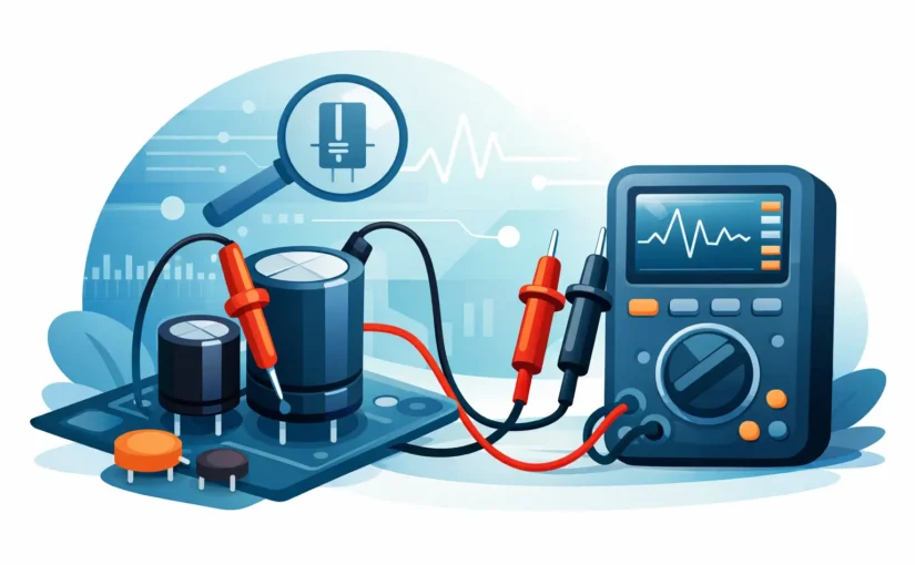
A capacitor can measure close to its marked capacitance and still be the reason a power supply oscillates, an LED driver flickers, or a digital rail collapses under load. Equivalent series resistance, or ESR, exposes losses that a capacitance-only measurement can miss. Knowing how to test capacitor ESR correctly means controlling the test setup, selecting a meaningful frequency, and comparing the result to a relevant specification rather than treating one resistance value as universally good or bad.
What capacitor ESR measures
An actual capacitor is not an ideal capacitance. Its internal foil, electrolyte, terminations, dielectric losses, and current path contribute resistance and inductance. ESR is the resistive portion of that non-ideal behavior at a stated test frequency. It represents energy dissipated as heat when AC ripple current flows through the part.
For an aluminum electrolytic capacitor in a switching regulator, excessive ESR can create output ripple, poor transient response, and self-heating. For a multilayer ceramic capacitor, ESR is often extremely low, so fixture resistance and contact quality may dominate the measurement. Film capacitors, tantalum capacitors, polymer capacitors, and supercapacitors each have different expected ESR ranges and frequency behavior.
That last point matters. ESR is not a fixed DC resistance. A data sheet may specify impedance or ESR at 100 Hz, 120 Hz, 1 kHz, 10 kHz, or 100 kHz. A reading only has engineering value when its test frequency, signal level, temperature, and connection method are understood.
How to test capacitor ESR accurately
Begin with safety and component condition. Remove power from the circuit, discharge the capacitor through an appropriate resistor, and verify residual voltage with a meter. Never place an ESR meter directly across a charged capacitor. A stored charge can damage the instrument and create a serious safety hazard, particularly in high-voltage power supplies or large bulk capacitor banks.
For the most reliable result, test the capacitor out of circuit. This isolates the device from parallel capacitors, semiconductors, inductors, and low-resistance PCB paths that can distort an impedance measurement. In repair work, in-circuit ESR testing is often useful as a fast screening method, but it is not definitive. A suspicious in-circuit result should be confirmed after lifting one terminal or removing the component.
Use a meter that measures impedance parameters at a known AC test frequency, not a basic ohmmeter. A DC resistance range will initially show charging behavior and then may drift toward overload. That observation can identify a shorted capacitor, but it does not measure ESR. An LCR meter, dedicated ESR meter, or precision handheld instrument designed for component characterization applies an AC stimulus and calculates the equivalent series parameters.
Before connecting the capacitor, compensate the test fixture. Short the probes or Kelvin contacts and perform the instrument’s short correction if available. For measurements of low ESR, open correction can also be necessary to remove stray capacitance and leakage in the fixture. Compensation should be performed using the same leads, connector, probe spacing, and measurement range used for the test. A low-milliohm measurement made with uncompensated leads can be a measurement of the leads rather than the capacitor.
Direct-contact tweezer instruments are particularly effective for small SMD capacitors because they reduce lead length and allow stable contact at the terminals. For radial or large can capacitors, use short Kelvin clips when possible. The force and cleanliness of the connection matter: oxidized leads, probe pressure, and a loose clip can add resistance that looks exactly like capacitor ESR.
Select a test frequency that matches the decision
Match the test frequency to the component specification or its operating environment. If an electrolytic capacitor is specified at 120 Hz, measure near 120 Hz for incoming inspection against that limit. If the capacitor is used on a 100 kHz switching rail and its data sheet provides high-frequency impedance data, a higher test frequency is more representative of the application.
A single frequency cannot answer every question. Low-frequency testing is useful for comparison with many electrolytic data sheets, while higher-frequency measurements can reveal performance relevant to switch-mode power supplies. At sufficiently high frequency, lead and fixture inductance become significant. The measured parameter may transition from capacitive behavior toward resonance, and reporting only ESR without phase or impedance context can be misleading.
Control temperature and measurement time
ESR changes with temperature, especially in electrolytic capacitors. A cold capacitor can exhibit much higher ESR than it will at normal operating temperature. Conversely, a part warmed by ripple current may test favorably for a short time while still having limited remaining life. If the result is near a pass/fail limit, record ambient temperature and allow the part to stabilize before making a disposition.
Allow the instrument reading to settle, but do not confuse a stable display with a valid result. Auto-ranging meters can briefly change test conditions during range selection. Once the reading settles, confirm that the displayed equivalent model is series resistance and that the selected frequency is documented. In production or quality-control work, those settings belong in the test procedure, not in operator memory.
Interpreting an ESR reading
The correct benchmark is the manufacturer’s data sheet, preferably the maximum ESR or impedance specification at the same frequency and temperature. If no specification is available, compare the reading with a known-good component of the same series, voltage rating, capacitance, package size, and approximate age. Comparing unlike capacitor technologies is rarely useful.
High ESR is usually the failure mode technicians seek, but low ESR is not automatically proof of a healthy part. A shorted capacitor can read extremely low resistance, and a ceramic capacitor with a cracked termination may behave intermittently under mechanical stress despite a normal bench reading. Check capacitance, dissipation factor when available, leakage where applicable, and the circuit’s actual ripple waveform when the fault remains unresolved.
A practical interpretation might look like this: an electrolytic capacitor specified at 0.08 ohm maximum at 100 kHz should not be accepted based on a 0.08-ohm reading measured at 1 kHz with long clip leads. The apparent match is accidental because the measurement conditions differ. By contrast, a compensated four-wire measurement at the specified frequency provides a defensible basis for an acceptance decision.
In-circuit ESR testing: fast, but conditional
In-circuit testing is valuable when troubleshooting densely populated boards, particularly when access is limited or component removal risks pad damage. An ESR meter’s low AC test amplitude may avoid forward-biasing some semiconductor junctions, allowing rapid detection of a clearly degraded electrolytic capacitor without desoldering it.
The limitation is parallel impedance. Multiple capacitors on a power rail can make a failed unit appear acceptable because healthy capacitors lower the measured ESR. Parallel resistive paths can also force the reading downward. Inductors, transformers, protection devices, and IC output stages can produce results that do not represent the capacitor at all.
Treat an in-circuit measurement as strong evidence only when the result is clearly abnormal and the circuit topology supports the conclusion. If the reading is marginal, unexpectedly low, or inconsistent with symptoms, isolate the capacitor by lifting one lead or removing it. This is slower than probing in place, but it prevents a false pass from becoming a repeat repair.
Common errors that produce false ESR results
The most common error is using a two-wire connection for a very low-ESR device. With two wires, probe and contact resistance are included in the result. Kelvin measurement separates the current-carrying and voltage-sensing paths, greatly reducing this error. For milliohm-level work, it is not a luxury; it is a requirement.
Another error is ignoring capacitor technology and package size. A small ceramic capacitor may have ESR far below that of a similarly valued electrolytic capacitor, while a high-voltage film capacitor may exhibit different frequency behavior from either. Use the component’s construction and intended duty to set expectations.
Finally, avoid testing a component that has not been fully discharged or has been removed from a hot circuit without allowing it to cool. Good metrology begins before the probes touch the part. Clean contacts, controlled connections, correct compensation, and traceable instrument calibration determine whether the number on the display can support a repair, production, or failure-analysis decision.
For technicians and engineers who must move from board-level triage to defensible component data, the fastest workflow is not simply measuring ESR. It is measuring it under conditions that make the result repeatable, comparable, and actionable.