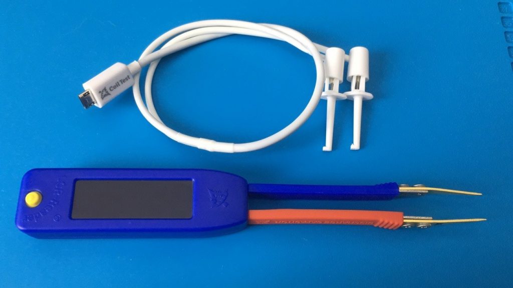
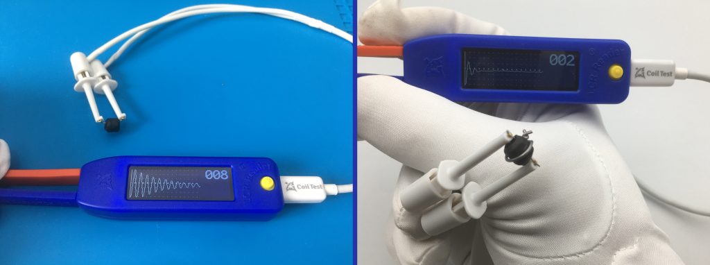
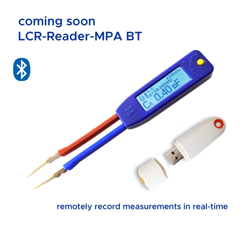
Tweezer-style LCR meters have revolutionized surface-mount device (SMD) troubleshooting since Siborg introduced the original Smart Tweezers in 2005. Today’s advanced instruments—including the LCR-Reader-MPA, R2, and R3—boast test frequencies up to 250 kHz, 0.1% basic accuracy, and comprehensive all-in-one multimeter capabilities.
However, engineers and technicians working with ultra-small RF components face a well-known physical limitation inherent to all tweezer-style instruments: parasitic capacitance and inductance in unshielded test leads.
To solve this challenge, Siborg Systems Inc. introduced patent-pending Open/Short Calibration Boards, enabling handheld tweezer meters to reliably measure passive components below 1 pF and 10 nH—territory previously reserved for expensive benchtop setups.
The Hidden Challenge of Tweezer Parasitics
Whenever an unshielded two-wire probe approaches a circuit component, parasitic fields form between the probe tips:
- Parasitic Capacitance: The air gap between the tweezer arms acts as a tiny capacitor. As the tips move closer together to clamp a smaller component, this mutual capacitance shifts.
- Parasitic Inductance: The physical loop created by the tweezer tines introduces residual series inductance.
In typical tweezer meters, parasitic offsets range from 0.014 to 0.249 pF for capacitance and 2.8 to 18.6 nH for inductance, depending directly on the distance between the tips.
While a 0.2 pF or 5 nH offset is negligible when measuring a 10 µF decoupling capacitor, it introduces catastrophic errors when qualifying ultra-small components. As Siborg demonstrated in IEEE publications (AutoTestCon 2022 and the IEEE Instrumentation & Measurement Magazine, August 2023), measuring an inductor below 10 nH without compensating for two-wire test fixture parasitics can lead to relative errors exceeding 100%.
How Siborg’s Offset Calibration Boards Work
Presented at Nepcon Tokyo and the SMTA International Conference in Minneapolis, Siborg’s proprietary calibration fixtures provide a repeatable, standard method for eliminating test-lead offsets.
The calibration boards are specialized dummy PCBs engineered with precision-spaced slots representing standard SMD footprints (such as 0201, 0402, 0603, and 0805):
- Geometry-Matched Compensation: Placing the tweezer tips into the exact footprint slot matching the target component fixes the probe spacing to that specific component width.
- Offset Nulling: The board allows the meter to determine the baseline parasitic offset at that exact mechanical spacing.
- Sub-pF Accuracy: By subtracting these offsets—or letting the meter’s firmware compensate automatically—measurement offsets drop below 0.01 pF for capacitance and 1 nH for inductance.
| Parameter | Standard Tweezer Offset | With Siborg Calibration Board |
|---|---|---|
| Residual Capacitance | 0.014 pF to 0.249 pF | < 0.01 pF |
| Residual Inductance | 2.8 nH to 18.6 nH | < 1.0 nH |
| Smallest Reliable Limit | ~10 pF / ~10 nH | < 1 pF / < 10 nH |
Running an Open/Short Calibration on LCR-Reader
On compatible instruments (such as the LCR-Reader-MPA, R2, and R3), executing a calibration cycle takes less than a minute:
- Insert the tips into the appropriate calibration slot on the board.
- Push and hold the control joystick to the right until you hear two beeps to initiate the calibration cycle.
Benchtop Precision in Your Pocket
Evaluating high-frequency RF matching networks, precision oscillators, and avionics circuitry no longer demands hauling out a dedicated benchtop network analyzer or four-wire bridge.
By pairing high-frequency test capability (up to 250 kHz) with dedicated Open/Short Calibration Boards, Siborg’s LCR-Reader family bridges the gap between field portability and laboratory-grade metrology.
To learn more about the LCR-Reader product family and calibration accessories, visit lcr-reader.com.